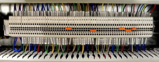
The current power distribution can be cleaned up. Multiple wires in a too small terminal block and separated relay board. Time to clean it up.
My build of the DDDAC1794 The 230VACpower distribution exists out of:
1x AC 230VAC coming from the mains connector
1x Power Supply for the DAC
1x Toroidal Transformer with dual secondaries for the clean an dirty digital supply
A (solid state) relay controlled by the soft power down controller
A momentary switch to start the system until the soft power down controller takes over
It would be nice if all could connect to a small power distribution PCB. And for size and stability the current relay replaced by a solid state relay.
power distribution schematic,
The Omron G3GMB-202P 5 volt version is a 2A solid state relay with zero-crossing detection. It already contains an internal resistor, so you can directly control with 5V/10mA.
The controller activating the solid state relay is described in Raspberry Soft Power Off. There a conventional relay is used which is directly activate after the controller is booted . This happens when the momentary switch is pressed, which temporary bypasses the relay until released. The start of the controller is fast enough to be unnoticed by the user.
With a solid state relay including switching on the 0 crossing this is different, while the momentary switch is closed the relay can’t be activated, it requires that some current can flow. And then it requires 1/2 a power cycle + 1 mS = 11mS. The system load (on the dirty 5V supply) is required to run at leased this time without AC to startup the solid state relay, before dropping below the 4.5VDC. That will not be a problem.
Next is to design a small PCB with those components:
PCB Layout
An impression of how the final result would look:
PCB Render with Kicad
But before we create a real PCB, lets first create a proto to see to see if we are satisfied with the practical use.
proto top side
For safety remove unused pads between the phase, neutral and control signals:
proto bottom side
And mounted in the actual DDDAC 1794:
proto mounted to the side panel of the enclosure
It works great and organize the power distribution in a neat way. It is time to order a real PCB. With the current proto in place I’m not in a hurry, so lets order it at oshpark with their famous PCB color.
OSHPark PCB
In case you also want to order a PCB, the PCB is shared at oshpark. OSHPark supplies a great quality at nice price, only it take a while be fore the good are delivered.
Update: September 26th the PCB’s have finally arrived:
2020-09-04: The custom sox recipes patch has been accepted by MPD on the master branch! 2020-09-14: The custom sox recipes are part of the upcoming moOde 7.0.0 release. MoOde even provide a nice GUI for it.
MPD can use the famous soxr library for resampling. Soxr is very flexible with the configuration of the resampler. Only MPD only provide the default recipes with the quality setting.
You can find a lot on internet about the usage of soxr or sox (the commandline version of soxr) , including a kind of measurements.
The patch mpd-0.21.x_soxr_customrecipe.patch (or for mpd-0.22~git) will add settings to MPD section of the resampler. In only unlock the already present settings in soxr, the functionality of sox is untouched.
Setting
Description
default
precision
Number of used bits [16|20|24|28|32]
20 (matches HQ)
phase_response
0 =MINIMUM_PHASE, 50=LINEAR_PHASE, intermediate is between those.
50
passband_end
Original bandwidth of source used (%, < 100)
95.0%
stopband_begin
(% > 100)
100.0%
attenuation
Lowers the source to prevent clipping. Expressed in db.
0 db
flags
Bit fields: 01 ROLLOFF_SMALL 0.01 dB 01 ROLLOFF_MEDIUM 0.35 dB 02 ROLLOFF_NONE For Chebyshev bandwidth. 08 HI_PREC_CLOCK Increase `irrational’ ratio accuracy. 16 DOUBLE_PRECISION Use D.P. calcs even if precision <= 20 32 SOXR_VR Variable-rate resampling.
0
To enable the custom recipe the quality should be set to "custom". If another quality is selected and the custom settings are still present you will get warnings in the MPD log about unused settings.
2020-09-14: The MPD soxr selective resample modes are part of the upcoming moOde 7.0.0 release. MoOde even provide a nice GUI for it.
Earlier I wrote about moOde with MPD Selective Resample about sox and resample. With selective resample takes in account if source sample rate is multiple of 44.1kHz or 48kHz. With selective resample the target sample rate is a integer multiply of source sample rate.
Sox with integer ratio only cost 50% of the CPU resource. Sound wise maybe less artifacts are introduced, but that is up to you and your ears to decide.
The selective resample could only be turned on or off. With a new patch some more flexibility is available.
The selective resample mode is set by combining several flags:
SELECTIVE_RESAMPLE_MODE = ADHERE_BASE_CLOCK and [UPSAMPLE_ALL | UPSAMPLE_ONLY_48 | UPSAMPLE_ONLY_44]
If non is set (0) then default scheme of sox is followed, resample (up and down) everything to the provided target rate.
If the resampled target rate should be a multiple of the source base rate can be set with the flag ADHERE_BASE_CLOCK.
When to resample a source:
UPSAMPLE_ALL- Only upsampling.
UPSAMPLE_ONLY_48 – only upsampling sources below 88.2kHz.
UPSAMPLE_ONLY_44 – only upsampling when source is 44.1kHz or below.
Where the flags have the following value:
ADHERE_BASE_CLOCK = 0x08
UPSAMPLE_ALL = 0x03
UPSAMPLE_ONLY_48 = 0x02
UPSAMPLE_ONLY_44= 0x01
In table the behavior is shown for several source sample rates and target sample rate of 192kHz and 176.4kHz.
When resampling is used the output rate is shown bold. Note that using a target rate as expressed in a multiple of 48kHz behaves more natural then express in a multiple of 44.1kHz.
Use
To support this modes you need to patch your MPD executable. The patch is available for the latest 0.21.xx [24|25| and upcoming 26] releases and the 0.22~git development branch.
You can find the 0.21.xx patch here and the 0.22~git patch here.
Applying the to your MPD source tree:
cd MPD/src
patch -b -p2 < /path_to_the_patch/mpd_0.21.xx_selective_resample_mode.patch
After applying the patch, you can build your MPD executable.
If you have an MPD version with support for it, you need to add the following to the MPD configuration:
selective_resample_mode "4"
Note: If you switch back to a version with mode support remember to remove this line, else MPD will not start.
2020-09-14: More flexible version is available, see MPD soxr selective resample modes .The MPD soxr selective resample modes are part of the upcoming moOde 7.0.0 release. MoOde even provide a nice GUI for it.
Music Player Daemon is a daemon used in a lot of (Raspberry Pi) audio distributions. Including the one that I use; moOde Audio Player. MPD supports a bunch of plugins, including SoxR for high quality resampling. Which can be used for both up and down sampling.
The most common used audio sample rates are based on two ‘base’ clocks; multiplicity of 44.1 kHz or48 kHz. Typical matching sample rates:
44.1 kHz based: 44.1 , 88.2, 176.4, 352.8 kHz
48 kHz based: 48, 96, 192, 384 kHz
Is you resample to a different base clock, for example from 44.1 to 96 kHz, you will get a big performance penalty with SoxR. At least compared with from 48 to 96kHz. It takes twice the number of CPU resource than from 48 to 96 kHz.
In MPD you can configure a target sample rate. Lets say we configure MPD to upsample to 96kHz. This works nice for 48 and 96kHz source, only for 44.1 and 88.2 kHz the outcome is a little bit different. You can image that from 48 to 96 (ratio 2) is a lot easier than 44.1 to 96 (ratio 2.17). You Raspberry Pi agrees and is lot busier with 44.1 to 96kHz. Almost twice the number of CPU resources are used. I don’t dare to say something about the audio quality, I just focus of the used CPU resources.
Wouldn’t it be nice if the 44.1 is just upsample to the nearest round base sample rate? This is what the supplied patch will do.. You just provide the max, as specified in a 48kHz base sample rate and 44.1 based will just match to the closest (but lower) sample rate.
At the end of this articles the results of performance test are shown and includes the commands to reproduce it yourself.
moOde only supports the resample option by using the global audio_output_format setting. Due this the patch will introduce a global setting called selective_44k_resample.
This will not work with Volumio because it doesn’t use the global resample option audio_format option, but the one on the output device. Of course the supplied patch could be changed to also support output devices.
The patch is tested with moOde 6.4.2 and mpd-0.21.20. For building the patch the easiest way is to do it directly on your target. The build instructions below are based moOde build recipe.
If you are coming from a stock Moode 6.4.2 ( with mpd-0.20.16) you need to regenerate you library, due some changes in the mpd-0.20.21 code.
Usage
To use a MPD build with the selective_44k_resample patch:
Set audio_out_format to a multiplication of 48kHz like 96000:24:2 (Off course you have to make sure the target requested sample rate is supported by your output and/or DAC.).
Set selective_44k_resample is set to yes.
For use with moOde the first one is clear. Open the MPD Configuration page and set the wanted resampling options.
Moode MPD config Sox Resampling configuration
The second one is a little bit harder to do. moOdedoes support small subset of the available MPD settings, let alone new settings. And because moOde generates the configuration for MPD any manual made tweaks are overwritten.
We need to make a small change to MPD configuration generator.
I use myself another patch for moOde. That patch adds the possibility to add additional global and device MPD options by using the moOde web interface. There we can just add the option selective_44k_resample "yes" to the general parameters.
Custom Moode MPD Tweaks
Search in the file /var/www/inc/playerlib.php for the following two line in the function updMpdConf. With Moode 6.4.2 the function starts at line 1521.
Reboot your Pi to make sure the new code is used. After boot go the the mpd configuration page and press save to make sure the mpd configuration is generated. To be sure you can check if the settings is in the mpd configuration by executing the following command:
For quite some time I’m using the Allo Isolator for galvanic isolation between the Pi and the HifiBerry. Everything was upsampled to 192kHz and works great. No more cracks, deep dark sound.
Only when starting playing with different sample rates (44.1kHz based) MPD hangs. Before using the isolator it did work. If seems that something is wrong.
The HifiBerry Digi+ Pro has two crystals onboard; one for a multiplicity of 48kHz and one for multiplicity of 44.1kHz based sample rates. The crystal selection is done by using GPIO 5 & 6. Only GPIO 5 isn’t isolation by the Allo Isolator.
This can lead to two scenarios:
If the power supplies aren’t isolated (for example shared ground), it will work. Only your system isn’t isolated as it should.
If the power supplies are really isolated, GPIO 5 becomes floating. In my case this even damaged my crystal.
The image below illustrate the difference between GPIO6 (pin31) and GPIO5 (pin29).
Isolated vs not Isolated pin
Fixing the isolation
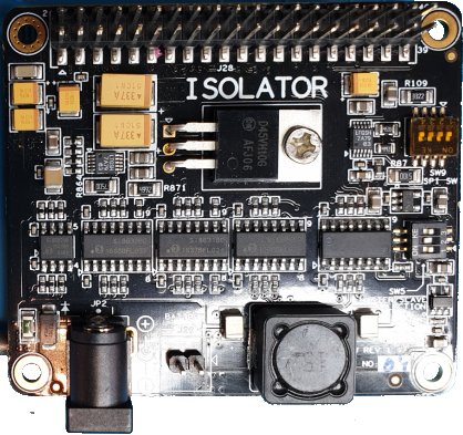
Lets first take a look at the Isolator. In red is shown which pin is isolated by which isolation ICs (Si8630, Si8631 and Si8502). Each pin has a certain fixed role; output(>), input(<) or bidirectional (<>).
Allo Isolator IO Pins vs Isolator Electronics
Also not clear from the Isolator documentation is that the SPI isolating works different from the GPIO isolation; SPI isolation means no connection at all. Yes that is also isolated, but not usable.
For the clock selection we need an unused output pin. Below is an overview of how my system is using the Pi IO header.
Raspberry Pi Io Header usage
GPIO16 (pin 36 ) looks like a good match.
Only the HifiBerry can’t be configured to use a different pin. We could rework the Allo Isolator in such way that GPIO 6 is using isolation electronics from GPIO16 (and disconnect GPIO16 from the Pi).
Steps to reuse the GPIO16 isolation electronics: – [bottom side] pin 29; cut trace to via – [bottom side] pin 36; cut connector from the solder pad – [bottom side] solder wire between pin 29 and pin 36 on the bottom side – [upper side] solder wire between pin 29 and pin 36 on the bottom side
I choose a different approach, which only requires one electronical modification to the Isolator; break the connection between GPIO5 upper and lower connector of the Allo Isolator. The trick is that we will make software modification so that the HifiBerry software driver will use the already isolated GPIO16.
Steps to take:
Electrical isolate GPIO5 upper and lower connector from the Allo Isolator.
Connect GPIO5 to GPIO16 on the isolated side with a jumper wire.
Create a software mod to use a different GPIO pin.
Isolated GPIO pin 5 from the Pi
First we have to make sure GPIO 5 (pin 29) is electrical isolated. On the bottom of the Isolator there is a via that connects GPIO5 from the bottom connector to the top connector. This via is connected with a very small trace going from to the solder pad of pin 29.
Just cut this trace with a small X-Acto knife or what ever for small knife you have. Probably you need to have some loupe of smartphone to see it clear enough, at least I did. You don’t need to remove the entire trace, just can scarf will do. Don’t forget to measure the connection between the upper and lower connector before and after to see if the cut is good enough.
Connect GPIO 16 to GPIO 5
Next we have to connect from the Isolator upper connector GPIO 16 (pin 36) to GPIO 5. You can solder a wire between solder pads of pin 36 and pin 29 and you are good to go. Because my HifiBerry has the additional male header installed, I did have another choice available; Just connect a jumper wire from pin 36 to pin 29 on the HifiBerry upper connector. No soldering required.
Jumper wire for connection between GPIO5 & GPIO16
Do you notice the connector in position P3? You can use this one to feed both the HifiBerry and the Isolator with clean 5V. In this way you can avoid the less available 6.5V for the Isolator. Both the HB and Isolator use own regulators for 3.3V, which what the actual chips are using.
Make the Pi use GPIO 16 for clock selection
Let the Pi HifiBerry driver use an other GPIO for the crystal selection is standard not available. To make this work we need to change the driver overlay a bit.
This involves the steps:
create a new overlay that support reconfigure the clock selection GPIO
configure the Raspberry Pi to use it.
Create a new overlay
Luckily it isn’t hard to make a new overlay which allow to configure the used pins. But you need to know a little about using the command line command of Linux. First login open a SSH session, for example with PuTTY.
Or alternative you can download the overlay here and just copy to the overlays directory on the SD card. It is build on Moode 6.4.2 with kernel 4.19.97-v7+ #1293.
Update 2020-09-14: In the article DDDAC1794 build is shown how the power supplies are connected. The Isolator isn’t fed with 6.5VDC. I use 2x times 5V(dirty + clean ) for it. The power supply for the Isolator is coming from the 5V connector on top of the Hifiberry. Therefor the extra regulator of the Isolator is bypassed and we can use a more common voltage of 5V.
2020-09-14 The upcoming 7.0.0 release of moOde contains another patch of me, that will make the one below obsolete.
The moOde Audio Player MPD configuration only support a very small subset of the available MPD options. The one that are supported comes with a very nice user interface. Only sometimes I just want to try unsupported or even new MPD options.
Just editing the mpd.conf isn’t an option, because Moode will overwrite the configuration file. You can work around it by modifying the Moode MPD configuration generator. But that isn’t very flexible. This article provide a patch to make experimenting with MPD a little bit easier by using the web interface of Moode.
On the bottom of the MPD configuration page an MPD Tweaks section is added.
When enabled two text input boxes are shown:
One for general parameters and one for the default output device. It doesn’t provide a very rich interface, but it beats changing the MPD configuration generator by hand. Multiple options can be set separated by ‘;’.
When the tweaks are disabled, the settings are still kept in the database only it isn’t used. This makes it easier switch on and off the settings.
Any parameter added to the MPD Tweaks General or Device parameters will override any parameter set by Moode it self.
In the final generated MPD.conf it is shown which parameters are coming from the MPD Tweaks settings:
This article is about building my own version of the DDDAC 1794 NOS DIY dac. Designed by Doede Douma. The NOS stands for Non Over Sampling DAC, without any filtering.
More info:
There is a massive thread diyaudio about the DDDAC 1794; nos-192-24-dac-pcm1794-waveio-usb-input. It can be a little overwhelming; it contains today almost 8000 messages. In 2017 it were only 6000 messages to read.
Audio Creative has published some nice article about this DAC. They are also the official channel to for available DIY DDDAC 1794 kits.
You can start a DDDAC 1794 NOS build very basic and depending on your budget and time extend it in time. I started my build in 2017 and completed most at the beginning of 2018.
In its most basic form it contains:
Power supply (kit available, but of course you can use your own)
Mainboard (sold as kit)
One or more DAC boards (sold as kit)
Output decoupling choice (default a cheap capacitor is supplied)
An enclosure and even that is an option.
In the most basic form only a SPDIF input is available. Other sources can be connected to an I2S input.
Specs of this build:
DDDAC 1794 subsystem exist out of:
1x Blue Mainboard.
2x DAC with Tent boards.
2x Cinemag 600/600CLI Transformers as output decoupler.
Raspberry Pi 3B
HifiBerry Digi+ Pro as I2S source for the DAC.
An Allo Isolator for galvanic isolation between the buildin Pi and HifiBerry + DAC.
The remainder of the article provide more detail of some of the modules.
Main board + DAC modules
The DIY kits supplied by Audio Creative are beautiful kits. You directly see that PCB are high quality. SMD components are already mounted on the PCB, you only need to solder the through hole components your self.
It includes silver wire for connecting the DAC with the main board. The kit also include Dale resistors for the I/V conversion. If you like to use silver solder, you can buy also a small amount from Audio Creative. You can find the construction documentation and more also on the DDDAC page of Audio Creative.
DDDAC1794 main and DAC module kitsAssembled main moduleAssembled DAC moduleMain with a single DAC module
Currently my system contains 2 DAC modules and have room left for a third DAC module.
Power supply
For the Mainboard and DAC boards a stock DDDAC 12V PS kit is used.
DDDAC1794 12V PS
The other components use 5V, but no DDDAC 5V PS kit is used for it. The 5V PS exists out of a clean 5V and a dirty 5V. The clean is used by the Hifiberry and the Allo Isolator (at least the clean part of the isolator). The dirty 5V by the Pi and other auxilary components. The 5V uses a toroidal transformer with secondary 2x6VAC, 30W. Followed by a dual DIYIHNK 4.17uV 5V/1A regulator. It uses a TPS7A4700 for regulation.
The Raspberry Pi is direct fed by the 5V dirty on the GPIO connector 5V, the USB PS connector is not used.
To the Hifiberry a connector on position P3 is added. This is used to fed the clean 5V to the Hifiberry and the Allo Isolator. If you had used the PS connector of the Allo Isolator it self, that voltage had to be 6.5VDC, because the voltage drop of the onboard 5V regulator.
By the way both the Raspberry, HifiBerry and the Allo Isolator all have onboard 3.3V regulators that are used to fed the electronics onboard.
In my build there is no connection between the dirty and clean ground. Make sure that in that case you also have the mod for the clock select.
Output decoupler
I replaced the default no name caps first by 2x MKT-Capacitor ax. 2,2µF ERD 1813 NOS. Later followed by Cinemag 15/15b transformers.
And finally settled with two Cinemag CLMI 600/600C to decouple the outputs. Both are nicely mounted to the side of the enclosure with a 3D printed mounted (Thanks Henk!).
Cinemag transformer mount
Raspberry Pi
Hardware
The Raspberry Pi is in this system not only important as a I2S source for the DAC, but the Raspberry Pi also controls most of the auxiliary modules like the display and source selection.
You can see this back in use of the Raspberry expansion header:
Raspberry Pi GPIO usages
The hardware is stacked as following:
On the bottom the Raspberry Pi
Followed by a PiFace GPIO Shim
Then the Allo Isolator
And finally the HifiBerry Digi+ Pro
The PiFace GPIO Shim makes it possible to breakout the GPIO and others pins, while continue stacking other boards.
PiFace GPIO Shim -Header Breakout
Special attention is needed for letting the Allo Isolator and HifiBerry work together and still honor the separation between the dirty and clean 5V modules. See an other article for more details.
All GPIO interfacing including the power supply for the Pi connected to the PiFAC GPIO Shim.
Operating System
Tested a lot of software distributions. Started with Rune Audio and currently Moode Audio 6.4.2 is used. It provides an easy to install system, a nice (web) GUI and is easy to mod.
It requires two configuration settings for make it work for this specific system:
First select the the HifiBerry Digi+ Pro as I2S device, which will require a reboot.
Second force to use 24 bit as output signal, source that aren’t 24 bit are converted. You can also provide a fixed upsample rate. See the article Selective Resample for an other interesting option.
Additional software for the display, source and soft power are handled in the previous paragraphs.
The base plate makes it easy to mount all components first on the base plate and then place the base plate in the case.
Base Galaxy GX
To see if everything fits the following floorplan is used.
floorplan
For designing the front and pack panel I used Front Panel Designer from Schaeffer. Within this application you can directly see the cost of the design and place an order with Schaeffer. Also it provides nice renders of the panels.
I wanted the display a little bit sunken in the front, but not the full 10 mm. Therefore also on the back some material should be extruded to bring the display more to the front.
front panelback panel with deepened location for the display PCB
I am very satisfied with the end result:
Source selection
The system has three sources:
Raspberry Pi, I2S
Digital 1, SPDIF or Toslink
Digital 2, SPDIF
Selecting the source is done with momentary switch next to the display. The switch is directly connected to the Raspberry Pi.
On power on default Digital 1 is selected. When the Raspberry is booted the Raspberry is default selected as source and the switch led is turned on. As long as the Raspberry is booting the screen will stay dark.
A short press will select the next source. If the Raspberry is selected a long press will pause or continue the current track.
The led current is to much for the Raspberry it self, the soft power down PCB contains a transistor to drive the led.
A dual relay module is used for selecting between I2S or SPDIF and selecting between Digital 1 or 2.
Dual Relay Module
The relay module is also controlled by same daemon on the Raspberry Pi as for controlling the display. The module is mounted against the back panel of the enclosure.
OLED Display
The system contains a small display to show source information.
The display specs:
Size :1.3″
Type: OLED
Resolution: 128×64
Interface: I2C
Driver: SSD1106
The display shows information about the Raspberry or the Digital Source (1 or 2):
If the Raspberry Pi is active the following information is show:
For controlling the display a daemon is running on the Pi. This daemon is written in Python and will work uses two libraries for the main functionality:
pyhton-mpd2 is used to connect to MPD for reading out information about the current song and playlist.
The daemon also contains the functionality to read the source button and control the led in the source button. Due using the MPD client library, you don’t have to integrate with Moode Audio itself. It will work on any MPD based or compatible audio player, even over the network if you want a separated display.
Soft power down
There is risk to corrupt the SD card of Raspberry Pi when it isn’t proper shutdown and I do power down my audio equipment when not in use, a solution is needed.
A software power down module is developed for this purpose. See the article Raspberry Soft Power Down for more information.
Part List
To give a clue about the number of parts and investment required hereby the list of my specific system.
Small parts like wiring, additional nut, bolts and some connectors are not on the list.
nr
description
subsystem
Supplier
count
price
total
1
DDDAC 1794 blue mainboard
dac
Audiocreative
1
€ 165,00
€ 165,00
2
DDDAC 1794 DAC board
dac
Audiocreative
2
€ 159,00
€ 318,00
3
DDDAC 12V PS
dac
Audiocreative
1
€ 94,00
€ 94,00
5
DIYINHK Ultra Low Noise PS
streamer
Diyinhk
1
€ 41,82
€ 41,82
6
Block RDK 30VA/2x6V
streamer
Conrad
1
€ 19,64
€ 19,64
7
Raspberry 3
streamer
SOSsolutions
1
€ 36,95
€ 36,95
8
SD Card 8 GB
streamer
SOSsolutions
1
€ 7,95
€ 7,95
9
Hifiberry Digi+ Pro
streamer
SOSsolutions
1
€ 42,95
€ 42,95
10
AC Main C14 Chassis part
case
Conrad
1
€ 5,25
€ 5,25
11
Fuse 20mm
case
Conrad
1
€ 1,20
€ 1,20
12
Torx147 Optical SPDIF Receiver 192k
case
Diyinhk
1
€ 3,35
€ 3,35
13
CinchConnector Rean AV NYS367-9
case
Conrad
1
€ 4,36
€ 4,36
14
CinchConnector Rean AV NYS367-2
case
Conrad
1
€ 4,36
€ 4,36
15
CinchConnector Rean AV NYS367-4
case
Conrad
3
€ 4,36
€ 13,08
16
Cinch-connector internal
case
Conrad
1
€ 1,48
€ 1,48
17
OLED Display 1.3″ I2C
case
Diymall by ebay
1
€ 8,51
€ 8,51
18
Galaxy Maggiorato GX388 330 x 280mm x 2HE 10mm front panel SILVER
During the a repair of an Amiga 2000 keyboard I didn’t found it very handy to use my Amiga as tester for a defect keyboard:
During testing, to prevent damage with unplug or plugin of the keyboard, it requires power down of the Amiga.Which takes a lot of time and proceedings (the boot, shutdown etc)
Change to damage the keyboard port of the Amiga if something was really wrong
So the idea began to take shape of we could build a simple tester. Next to me laying was a Arduino Uno with a Multi Functional Shield laying around. And the Amiga Keyboard protocol doesn’t seem to hard to me.
Hmmm lets first see if you one else already did use an Amiga Keyboard on an Arduino. And yes the is. The purpose of the solution in the thread, is using the Amiga keyboard on other computer with Arduino as USB adapter. I used the script provided in message #90 as basis. It is original written by Janne Lof, but I can’t find the original reference. You can find the modified Arduino sketch at :
The Arduino Uno doesn’t support using the device as an USB hid. So first get rid of the the USB code and use an Serial.print to test if it works. And then switch to use the 4x 7 segments display.
Amiga 2000/3000 pin out
Lets connect a suitable connector for my Amiga 2000 keyboards. See AMIGA Keyboard connector pin-outs for pin-out of the other models. Due the shield already taken a bunch of pins, we need other free pins to use. Preferred some that are already available on the unused headers on the shield.
#define PIN_KLCK 6 // black (was 8)
#define PIN_KDAT 5 // brown (was 9)
For testing we use serial port, after testing the serial code is disabled. In the Arduino IDE under the Tools menu is a serial monitor. In setupmake sure Serial.begin(9600);is called. Ok that seems to work. Now the script will be changed to:
Show the amiga (hex) keycode on the two first digits of the display.
On a key press the dp(=point) on the last segment will be on.
On a key release the dp(=point) on the last segment will be turned off again.
If an out of sync situation occurs the display show “____”.
In general it works well, but sometimes “____” or the key release doesn’t react. Lower the time of kdat low seems to improve it, but set to short, according to the protocol, some hardware will refuse to work it.
My kids like easy coding with Scratch or mBlock. I found a nice Arduino shield for them to play with, only it could only be programmed with the Arduino IDE. Luckily mBlock provided a way to extent the mBlock environment.
The Arduino Multi Function Shield is a low cost shield provided by several suppliers. It contains a lot of basic IO for fun experiments. Typical the stuff you put normally first on a breadboard.The shield contains:
mBlock is a Scratch like IDE for making computer program, but it also supports several hardware platforms like the mBot, but also Arduino. My kids use this very accessible environment for the mBot, but is also support other hardware like the Arduino Uno.
mBlock environment web or app
mBlock Extension
To make the it able to use the Arduino shield in mBlock, a so called extension should be created for it in the mBlock online extension builder. When a extension is finished it can be published for approval. In the will so up in the Extension store.
In the extension center you create for a certain category a number of blocks.
new block in the extension builder
Each block can be hooked to matching C code for :
declare
setup
code
set led block configuration
For use it needs to be added to you mBlock environment. Unless you want to hack the extension yourself, you can use the MF Shield from the extension center.
MF Shield extendsion in the extension center
MFS Blocks
Below are the new blocks created for use with the MF Shield and are available in mBlock:
Overview of the MF Shield blocks in mBlock
The MFS library use a Timer in the background to update the leds, display segments and read the switches.The MFS library has a very nice way to read the switches; it puts every event in a round robin queue.The function MFS.getButton get the first one from the queue. Using this function several times in the main loop is a bad idea. That’s why the functionality is splitted in two;
get first entry in the queue – (get button state block)
eval if a certain key is pressed – (is button [x] [pressed] in [button state] block)
Read the switches
If you only have one button test you can use the get button state block directly in the eval block. If you have multiple you first need to store the button state into a variable and use that variable in the eval:
Only one switch test in your program:
Use multiple switches in your program:
Leds
Potentiometer
Display
Try-out extension
Try out the extension before it is published (before is applied to and approved by the mBlock Des):
Click in the extension editor download
Save it own disk
Open mBlock
Open an explorer to the downloaded extension
Drag and drop it onto mBlock
Restart mBlock
Chose add extension
Add the MFS extension to your project (project device has to be an Arduino, only tested with the Uno)
If display segments are used with raw data (instead of display test use set display segment) you can enable each led of the segment. A-DP are the bits of the segment.
Some time ago I was offered a defective Amiga keyboard. It was Amiga 2000 Cherry Keyboard, one of the more rare Amiga 2000 keyboards. The previous owner informed me that the keyboard was not working at all.
This keyboard has several unique distinctive features:
Red Amiga keys (notice different location of those keys; there is space between those keys and the space bar).
Uses Cherry MX switches.
Double shot caps (except for the Amiga keys); not printed symbols, but two colors of plastic. Just like my C64 keyboard.
Small function keys.
Let’s see how far we can get the keyboard working again.
First examination
An inspection of the exterior:
Plain label on the front with “Amiga 2000”
Slightly yellowed
No label of id on the bottom
US QWERTY layout
Nice red Amiga keys !
Big ass Return key
Six clickers for opening the case
Not the ergonomic connector seen with others, but I found pictures with exact the same connector and cable so it seems to be the original.
Foots the bottom are missing
In my opinion, the keyboard wobbles on the outer edges
It is opened before; the six clips looks scratched
After opening the case and inspecting the internals:
Identification:
On the PCB component side 4 labels:
879/00 11883 13047552 (white upper left corner)
Unreadable (orange above the F1/F2 keys)
197 (yellow above the F7/F8 keys)
Unreadable (white left from the cursor key > )
On the solder side of the PCB as part of the PCB: Cherry 601-1435 Rev.: 0.2
No metal plate to support the PCB and add a nice weight to the keyboard.
Old school lower quality pertinax PCB; the old brown stuff.
Damage to the traces and some pads
Normally on those two pads the shield cable is soldered.
Can be that there was to much mechanical stress and the traces came lose from the PCB.
The mask indicates that there should be 2 capacitors. But I’m not sure that it was ever there. Lets see if t can find photo’s of this area.
Due the damage above someone resoldered the shield cable
The solder looks no good.
It is connected to pin of a capacitor.
The trace did come loose from the pcb. (to hot welding temp used ?), so the capacitor is now floating.
Both pins pf the 6 MHz crystal looks to have bad solder joints. One is even loose.
PCB lacquer looks a little lumpy, nothing serious just aesthetic.
No other damage visible.
Some research
After some searching found that the PCB ID Cherry 601-1435 matches with Amiga Commodore G80-0879HAU (601-1435) Cherry MX Black. It looks like that this keyboard is only used for the first batch of Amigas A2000A r4.x (the German design) from 86/87. The USA based sites find it a rare keyboard, but I think in Europe it isn’t because the A2000A is never sold in the states. Nice article can be found on AmigaLove. On deskthority information and pictures are available.Based on one of that pictures:
It has the same cable and connector, so it it original. On AmigaLove it was stated that this keyboard has the ergonomic connector, but this isn’t always the case. The one on deskthority and mine obtained models have a different connector.
The pads (with the broken traces, on the images below the 4 holes right next to yellow wire) which are empty on my board are also empty on that picture, good news.
Image from deskthority.
It seems that the PCB from deskthority doesn’t have the brown pertinax PCB.
The keyboard controller is made out of one of the first Intel 8 bit micro controllers (MS48 family):
Intel P8049AH (from 1977!)
ET 2716 Q1 (EPROM) with version 467
74LS373
74HCT373
Crystal 6MHz
The good thing about this is; no special MOS chips involved. All later Amiga keyboards use a MOS keyboard controller. The P8049AH contains 2k ROM, it isn’t used and relies on an external EPROM for the program.
I’m not sure about it, but it looks that this keyboard PCB is produced by Cherry Germany and not Commodore. Cherry did use this controller logic with several of their other products. They used instead of P8049AH also P8039AH, which is the same model but without internal ROM. Are pin compatible and can de swapped. It is configured to use the external EPROM.
The repair attempt
Shield
Based on the damage found, I think that the ground is floating and not connected to the PCB. The damage is related to relocated and resoldered (with to much heat?) of the wire connected to shield carton. Lets first correct that by cleaning up add add a bridging wire and remove the shield wire.
Ok caps light will now turn on at startup, but further it is still dead. Remove the bridge wire again and provide are more permanent solution;
Desolder the bridge wire
Scrap the lacquer for 3mm from trace that is left, but unconnected. Clean it with IPA, followed by flux with heating.
Again clean with IPA and apply flux.
Finally apply solder to the fresh cleaned copper.
Measure the connection
If keyboard is working again restore the shield wire by an little bit more easy to handle wire and also solder it on an different location.
Crystal
Next in line are the bad solder joints on pad/pins of the crystal. Not clearly visible in the image, but both pins are loose in solder joints. Just reflow the joints. To be sure measure the crystal is still working check it with the scope. And the answer is no. Maybe are the bad joints related to the mounting method, it hings on the legs and provide mechanical stress to the joints. The crystal will be replaced and will get little support of a drop soft (removable) glue.
EPROM Check
Next I will check it the EPROM is this functioning. For this I need an ROM image to match it against. This ROM is part of the Mame emulator a2000kbd_g80_us device. Size and checksums are provided:
name
size
crc
sha1
467.u4
2048
fb92a773
e787dc05de227f30a47ac5b9ee7a355c2e9e693b
This source did only provided the checksums, but not the ROM it self. The checksums are just fine for verify that the content of the ROM is still ok, but I like to also have the image itself. Luckily the site retroroms provides all Mame roms including the a2000kbd_g80_us.zip rom.First check if the ROM matches the checksums provided above. I use the hex editor HxD for such things. Because the ICs on the keyboard PCB are soldered without sockets, I first have to desolder (so happy with my ZD-915 desoldering station !) the EPROM.
Now I can verify, using an old programmer Leap EP-1 with Windows 98 SE, if the content of the EPROM matches the ROM image. And yes it does.
The EPROM checks out to be ok!
New Shoes
Instead of soldering it back, I decide to first solder an DIL socket back. Normally maybe not wise for keyboard to have ICs in sockets, but it makes future repair, checks and replacements easier. And this keyboard will get an easier life that the previous 30 years, therefore I trust that the IC will remain in its socket. And while busy with the iron lets give the other ICs also some shoes 😉
Spare parts
To be prepared see if I can get replacement parts, if needed.T he two 74xxxxx can be obtained from normal electronics stores. The CPU and EPROM is different story. Luckily there is a company specialized in such parts and ask reasonable prices. This company is Slawmir in Poland (also present on ebay, use the filter “seller:slawmir” ). An used P8039AH CPU and an ET 2716 EPROM will cost less then €5, lets order it for just in case we need it.
Schematic
Lets check the traces again, this time not only optical but also with the multi-meter. To make sure everything is tested correct a schematic of the electronics would help, I could not find it only. Lets recreate an schematic with KiCad. The PCB is self and the MCS-48 Family User’s manual are used to create the scheme. Is fairly basic setup:
Timing circuit .
Reset circuit.
Extern EPROM with latch for the lowest 8 bits.
Additional 8 inputs with a HCT373.
Use port P1 and part of port P2 for IO.
The kclock and kdata use both two pins; one output and an interrupt input.
The only tricky one is the reuse of the for lowest bits of P2 for both address and IO.
Now we have a schematic, additional I will also create the PCB layout with only component placement (no traces):
Both together make it very efficient to measure the connections without constant following the trace. And because the ICs already have sockets, let get the IC’s out to make the measurement even more easy and have no risk at damaging the old ICs.Just following the connection from pin to pin in the scheme to see if it works. Also check for double connections.
Trace Connections
We start with measuring only the area where the control electronics are, not the connection of every Cherry MX switch. I only will follow a few of those just see if at least one switch and its connections are correct. After measuring with the multimeter at least the A8 and A9 signal seems not connected to the EPROM. Finally with an inspection with 8x zoom showed very thin crack in the upper layer of the underside of the PCB.The crack is spread over 6 traces, one affected (A10) is still working. Clearly I need some better tooling for visual inspection.
Restore A8 & A9
First quick fix is to temporary add some bridge wires for A8 and A9 to see if this is the last error to fix. Boot with AmigaTestKit (formerly SysTest) And yes it works! Only the O and Z aren’t working, probably due the other broken traces (checked the switches).
Remove the coating from the damaged traces and cleanup with IPA and flux.
Then apply flux and with a very small soldering tip apply some tin on it. Steady hand required each trace is less then a 0.4 mm width.
And after soldering each broken trace all keys work again.Finish this with a strong lacquer to seal it.
Cleaning and put it back together again
Time to clean the enclosure and keys. All keys are removed and cleaned piece by pieces.
Now the keys are removed, you can seen that it are really double shot keys; no printed symbols, but used two different colors of plastic. This guarantees that the colors will not fade in time or use. Only the Amiga keys are an exception, those are still printed. All A2K,A3K,A4K keyboards that come after this model all have printed symbols.
Hmm I don’t like the way the spacebar is moving. It seems that one guidance of the stabilizer is broken.
Use some power glue to restore it and add some soft (removable) glue to outside to provide some support.
Due the clips of the enclosure closing and the the tight space for the keyboard cable, I use the following order for putting the enclosure back:
Take the upper part of the enclosure.
Place it up side down.
Place the PCB.
Make sure the keyboard cable is placed correct .
Place the two internal screws, but not fully tight them.
Move the PCB to most up.
Now you can tight both the screw.
Take the lower part of the enclosure
Place it up side down
Place the shield (with metal folly to the plastic)
Fix it with some tape or fold the folly in place with your hand
Now you can place both together and press the clips
And the end result:
Bonus
Because the schematic and PCB layout are created in KiCad, we also now have a nice render of the PCB. Including identification of the problems areas. Each of the three areas was enough to make the keyboard not work. This is the first I had to repair something with a triple error with the same effect; a dead keyboard.


