AMIGA Keyboard tester

AMIGA keyboard tester

During the a repair of an Amiga 2000 keyboard I didn’t found it very handy to use my Amiga as tester for a defect keyboard:

  • During testing, to prevent damage with unplug or plugin of the keyboard, it requires power down of the Amiga.Which takes a lot of time and proceedings (the boot, shutdown etc)
  • Change to damage the keyboard port of the Amiga if something was really wrong

So the idea began to take shape of we could build a simple tester.
Next to me laying was a Arduino Uno with a Multi Functional Shield laying around. And the Amiga Keyboard protocol doesn’t seem to hard to me.

Hmmm lets first see if you one else already did use an Amiga Keyboard on an Arduino.
And yes the is. The purpose of the solution in the thread, is using the Amiga keyboard on other computer with Arduino as USB adapter. I used the script provided in message #90 as basis. It is original written by Janne Lof, but I can’t find the original reference. You can find the modified Arduino sketch at :

The Arduino Uno doesn’t support using the device as an USB hid. So first get rid of the the USB code and use an Serial.print to test if it works. And then switch to use the 4x 7 segments display.

Amiga 2000/3000 pin out

Lets connect a suitable connector for my Amiga 2000 keyboards. See AMIGA Keyboard connector pin-outs for pin-out of the other models. Due the shield already taken a bunch of pins, we need other free pins to use. Preferred some that are already available on the unused headers on the shield.

#define PIN_KLCK 6 // black (was 8)
#define PIN_KDAT 5 // brown (was 9)

For testing we use serial port, after testing the serial code is disabled. In the Arduino IDE under the Tools menu is a serial monitor. In setup make sure Serial.begin(9600); is called. Ok that seems to work.
Now the script will be changed to:

  • Show the amiga (hex) keycode on the two first digits of the display. 
  • On a key press the dp(=point) on the last segment will be on.
  • On a key release the dp(=point) on the last segment will be turned off again.
  • If an out of sync situation occurs the display show “____”.

In general it works well, but sometimes “____” or the key release doesn’t react. Lower the time of kdat low seems to improve it, but set to short, according to the protocol, some hardware will refuse to work it.

For reference it is nice to have the Amiga Keyboard codes at hand:

My Mitsumi based Amiga 2000 keyboards works fine, but the Cherry based version doesn’t. That board takes to much power from the USB 5V.

On my bucket list for further improvements:

  • Joystick test
  • Mouse test
  • Maybe on other SPI or I2C display for more rich feedback.
  • How to deal with the Cherry board (separated supply … ?)

mBlock Arduino Multi Function Shield

My kids like easy coding with Scratch or mBlock. I found a nice Arduino shield for them to play with, only it could only be programmed with the Arduino IDE. Luckily mBlock provided a way to extent the mBlock environment.

The Arduino Multi Function Shield is a low cost shield provided by several suppliers.
It contains a lot of basic IO for fun experiments. Typical the stuff you put normally first on a breadboard.The shield contains:

  • 3x push switches
  • 4x leds
  • 1x buzzer
  • 1x potentiometer
  • 1x 4 segments 3461 BS display 
  • And some interfaces for optional io/sensors

You can code it your self in the Arduino IDE or use an existing library like the arduino-multi-function-shield library

mBlock

mBlock  is a Scratch like IDE for making computer program, but it also supports several hardware platforms like the mBot, but also Arduino. My kids use this very accessible environment for the mBot, but is also support other hardware like the Arduino Uno.

mBlock environment web or app

mBlock Extension

To make the it able to use the Arduino shield in mBlock, a so called extension should be created for it in the mBlock online extension builder.
When a extension is finished it can be published for approval. In the will so up in the Extension store.

In the extension center you create for a certain category a number of blocks.

new block in the extension builder

Each block can be hooked to matching C code for :

  • declare
  • setup
  • code
set led block configuration

For use it needs to be added to you mBlock environment. Unless you want to hack the extension yourself, you can use the MF Shield from the extension center.

MF Shield extendsion in the extension center

MFS Blocks

Below are the new blocks created for use with the MF Shield and are available in mBlock:

Overview of the MF Shield blocks in mBlock

The MFS library use a Timer in the background to update the leds, display segments and read the switches.The MFS library has a very nice way to read the switches; it puts every event in a round robin queue.The function MFS.getButton get the first one from the queue. Using this function several times in the main loop is a bad idea.
That’s why the functionality is splitted in two;

  1. get first entry in the queue – (get button state block)
  2. eval if a certain key is pressed – (is button [x] [pressed] in [button state] block)

Read the switches

If you only have one button test you can use the get button state block directly in the eval block. If you have multiple you first need to store the button state into a variable and use that variable in the eval:

Only one switch test in your program:

Use multiple switches in your program:

Leds

Potentiometer

Display

Try-out extension

Try out the extension before it is published (before is applied to and approved by the mBlock Des):

  1. Click in the extension editor download
  2. Save it own disk
  3. Open mBlock 
  4. Open an explorer to the downloaded extension
  5. Drag and drop it onto mBlock
  6. Restart mBlock
  7. Chose add extension
  8. Add the MFS extension to your project (project device has to be an Arduino, only tested with the Uno)

If you to update the extension repeat step 1-6.

Resources:

You can find the extension on:

Other handy links:

If display segments are used with raw data (instead of display test use set display segment) you can enable each led of the segment. A-DP are the bits of the segment.

Raspberry Soft Power Off

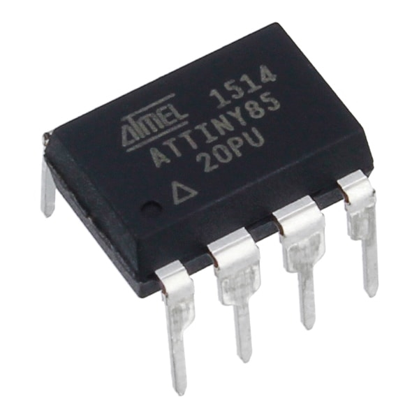
There is risk to corrupt the SD card of Raspberry Pi when it isn’t proper shutdown and I do power down my audio equipment when not in use. The Soft Power Off module, based on a ATtiny85, provides a solution for it.

There are some power down solutions for the Pi available, but none was suitable for my needs:

  • One button for power on and off.
  • Soft power down, that waits until the OS is also stopped.
  • Identification that the Pi is booting (blinking led)
  • identification that the Pi is shutting down (blinked led)
  • No power use when off, also no standby power.

The idea to use a small controller the ATtiny85 to manage the soft power control process. It controls a relay in combination with a double pole momentary switch.
When the power switch is pressed one pole is used to bypass the relay, before the switch is released the controller is booted and activates the relay to ensure the power stays on.

At the same time the power LED in the switch start blinking and the Raspberry starts booting. After a while the Pi will toggle a GPIO pin to shows it is booted. In response the ATTiny stops blink the led and turns is on.

Soft power down circuit based on ATtiny85

When you power down by pressing the momentary switch again, the second pole is connected to the soft power down circuit. That delegates the power down request to the Raspberry Pi, and the LED in the switch starts blinking. When the Pi confirms the power down by toggling a GPIO pin to 0, the power circuit inactive the relay power relay.

When the Pi shutdown is initiated from the Pi is self, the same process is used. Only there is no blinking LED to provide feedback.

The process is shown in the following state machine:

Proof of Concept

Proof of concept is first created in with tinkercad , due it’s online a simulation, including with the programming of the tiny with Arduino.

tinkercad electronics with Arduino simulation.

Instead of a Pi a switch and LEDs are to simulate the sensor and actuators. After the successful Tinkercad test a breadboard is used for further testing.

Test board wiht the soft power down circuit.

During the testing on testing breadboard it was clear that Arduino bootlader is to slow. It would require that you hold the switch button for several seconds. After you remove the bootloader it boots in a blink, you will not notice it when pressing the button. The downside is that instead of cheap USB board, now you will need an In System Programmer. Fortunately you can transform an other Arduino, like an Uno, into an ISP .

The sketch is directly available in the Arduino IDE under examples with the name ArduinoISP.

Final Electronics

Finally we can build the real electronics. It exists out of an relay board with a controller on experimental PCB board next ot it. It’s on the to do list to create PCB to replace the relay and power down PCB, for now it’s good enough.

The schema and Tiny code can be found in my git repo with the dddac1794 build.

Raspberry Pi configuration

The solution provided here works of Raspberry with a OS derived from Raspbian Buster Lite 10.

To let the Raspberry Pi place nice with the soft power off module it requires 2 GPIO pins:

  • output pin; 1 is booted
  • input pin; 1 is request power off

In my system GPIO17 is used for the power state and GPIO22 for the request power off.

Of course we could write a little daemon for it, but the Raspberry hardware overlays already provide functionality for it.

The gpi-shutdown overlay provides a way to shutdown the Pi based on the toggle of an GPIO pin. And the overlay gpio-poweroff provide a way to show the current state with a GPIO pin.

If you add the following to lines to /boot/config.txt, after the next reboot this functionality will be active:

dtoverlay=gpio-shutdown,gpio_pin=22,active_low=0,gpio_pull=off
dtoverlay=gpio-poweroff,gpiopin=17,active_low

The power down request works fine. Only I don’t like that the power led stops blink direct after the start of the Pi. I would like that it stops blinking when the system is fully booted and ready to play music.

For that we needed to delay the activation of GPIO 17. Just using a cmd line command is attractive, but this gives problems with setting the power down state to 0. That should be as late as possible, preferable after the filesystem is umounted, which isn’t possible if you need to load command.

There is an alternative by loading the overlay ‘manually’. We just need to remove or comment the gpio-poweroff line in the /boot/config.txt and add a systemd service that loads the overlay instead.

Create a file in /home/pi with the name pipowerstate.service with the content:

[Unit]
Description=External softpower on/off
After=multi-user.target

[Service]
Type=idle
ExecStart=/usr/bin/dtoverlay gpio-poweroff gpiopin=17 active_low

[Install]
WantedBy=multi-user.target

To create the service:

sudo cp pipowerstate.service /etc/systemd/system
sudo systemctl enable pipowerstate
sudo systemctl start pipowerstate

Afterward restart your system to see if everything work as expected.

Update: I did build a custom PCB to replace the relay board by power distribution PCB with a solid state relay. See the post AC Power Distribution.