In the article DDDAC 1794 Build I describe my personal build of the DDDAC1794 NOS DIY DAC. Because it is a DIY project it is always on the move. Part 2 contains the updates since the previous article.
Changes are:
Add third DAC Module PBT
Used a LT3045 from LDOVR to replace the LF50 on the mainboard.
Power Distribution PCB
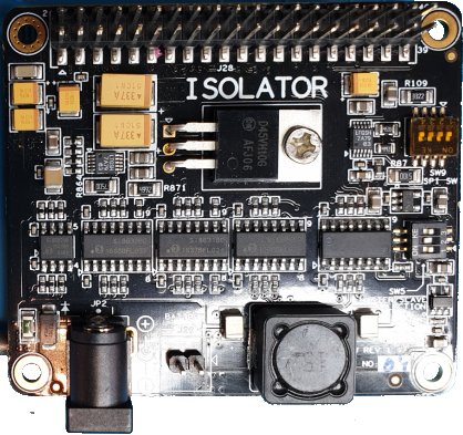
Used Ian Canada FifoPi Q3 to replace the combo Hifiberry Digi+ Pro and Allo Isolator.
The schematics and tweaks of the previous build are archived on in my Github repo under the tag build_hf_alloisolator.
Third DAC Modules PBT
With a third DAC module the maximum capacity is reached in my enclosure.
As always Audio Creative delivers fast and complete. Soldering only requires through-hole components so it is easy to do.
Within 30 minutes the DAC board is finished.
Just put this on the top one existing one.. Instead replacing the silver wire of the already existing boards, I just solder the silver wires with silver solder to top of the existing connections.
Next the value of the V/I Rload resistors needs to be correct. The value is 134Ω divided by the number of boards. For the 2 boards boards 68Ω is already used in place. Just putting a 133Ω in parallel with it will make an Rload of 45Ω.
After power the leds of the onboard tent regulator turn on so it looks like the mission succeed.
Next is calibration of trimmers. Both need to be adjust to 40mV on the test point. Which the voltage between the leg of the resistor next to the trimmer and common.
LT3045
The LT3045 from LDOVR is a 78xx/LFxx pin compatible power regulator.
We gonna use this regulator to replace the mainboard 5V regulator. There it is used to feed the logic for the I2S delayline, buffer and I2S/SPDIF selector. The SPDIF electronics and Tent clock are fed by separate regulators.
To fit the LT3045 you first have to desolder you current LF50, it sit just next to power terminal of the mainboard.
AC Power Distribution PCB
To cleanup the wiring for the power distribution and remove the current relay board, I created a small PCB. You can read about it in article below:
Apart from the hopefully soundwise improvements, replace the Hifiberry + Isolator with the FifoPi also reduces the building complexity a little bit:
Normal size screw terminals for the dirty and clean power.
Isolated and non isolated GPIO header, no need a GPIO for breakout between the Pi and Isolator anymore.
Nice F.UL connector for the I2S signals.
Downside is that the FifoPi form factor isn’t exactly the size of a regular Pi hat. Especially on the side of the SD card makes this it harder to replace you SD card.
The new FifoPi has stripped the LDO regulators from the PCB to allow your own PS solutions. The isolated part requires a clean 3.3V.
The voltage regulator I used to feed the Allo Isolator was a DIYHNK 4.7uV ultra low noise regulator based on a TPS7A4700. Luckily the TPS7A4700 is a programmable regulator and default a jumper is present to select between 5V and 3.3V. Other voltages can be made by adding jumpers to the available solder pads.
For connecting the I2S with F.UL connectors I ordered three (MCLK isn’t used) 6″ premade cables. Each cable contains a signal and GND as shield. On one side just cut of the connectors added a header for the I2S connector.
Because the power supplies between the FifoPi and the DDDAC are completely separated, it also requires that the ground is connected. By using the shield of one of the F.UL cables this is a very clean solution, very small GND path. In the image above this the white/green wire.
Use some hot glue to provide some additional support to the wires.
As probably known I’m moOde fan, which uses a regular Linux kernel for the Raspberry Pi. The used driver for FifoPi is the generic rpi-dac, which is actually for a PCM1794 (talking about coincidence ). Only the codec of this driver has a software limit of 192kHz, while the Pi supports 384kHz and also the FifoPi/ DDDAC1794.
I have created a small patch to increase the max frequency to 384kHz in the article below:
2020-09-17 Update: prebuild patched modules are available for moOde. 2020-09-30: The patched modules are part of the upcoming moOde 7.0.0 release.
In November 2017 the Raspberry Linux kernel is updated to support the 384kHz for the i2s bus. Before that time the stock kernel was limited to 192kHz and the generic i2s master driver rpi-dac still is.
With i2s bus the Pi can be used as master or slave. In case the Pi is used as a generic i2s master, the rpi-dac driver can be used. Only this driver is limited to 192kHz by the using of the pcm1794a codec.
This a little bit confusion confusing a generic driver but it use the pcm1794a codec. Therefor also limited to the pcm1794 sample formats and rates.
The use-case for the 384kHz support, is the use of an i2s reclocker connected to a DDDAC1794 NOS. The DDDAC1794 use a PCM1794, according to standard specs it only support up till 192kHz. Only when oversampling and digital filters are disabled, it seems you can go at least up to 384kHz. Any application note or specification which support this behavior would be welcome!
If you are using rpi-dac you can check this by running alsacap:
$ alsacap
*** Scanning for playback devices ***
Card 0, ID `sndrpirpidac', name `snd_rpi_rpi_dac'
  Device 0, ID `RPi-DAC HiFi pcm1794a-codec-0', name `RPi-DAC HiFi pcm1794a-codec-0', 1 subdevices (1 available)
    2 channels, sampling rate 8000..192000 Hz
    Sample formats: S16_LE, S24_LE
    Buffer size range from 64 to 131072
    Period size range from 32 to 65536

      Subdevice 0, name `subdevice
If you are willing to build your own kernel/drivers, you can enable 384kHz support by changing one line:
After the you patched the driver and use it, alsacap should should the new max sample rate:
$ alsacap
*** Scanning for playback devices ***
Card 0, ID `sndrpirpidac', name `snd_rpi_rpi_dac'
  Device 0, ID `RPi-DAC HiFi pcm1794a-codec-0', name `RPi-DAC HiFi pcm1794a-codec-0', 1 subdevices (1 available)
    2 channels, sampling rate 8000..384000 Hz
    Sample formats: S16_LE, S24_LE
    Buffer size range from 64 to 131072
    Period size range from 32 to 65536
Installing a patched module
In the my git repo you can find prebuild modules for the following raspberry pi kernels:
5.4.51-v7+
5.4.51-v7l+
5.4.61-v7+
5.4.61-v7l+
The prebuilds match the kernels from moOde release 6.7.1 and the upcoming 7.
The repo also includes an install procedure for installing the prebuilds or building your own.
The current power distribution can be cleaned up. Multiple wires in a too small terminal block and separated relay board. Time to clean it up.
My build of the DDDAC1794 The 230VACpower distribution exists out of:
1x AC 230VAC coming from the mains connector
1x Power Supply for the DAC
1x Toroidal Transformer with dual secondaries for the clean an dirty digital supply
A (solid state) relay controlled by the soft power down controller
A momentary switch to start the system until the soft power down controller takes over
It would be nice if all could connect to a small power distribution PCB. And for size and stability the current relay replaced by a solid state relay.
power distribution schematic,
The Omron G3GMB-202P 5 volt version is a 2A solid state relay with zero-crossing detection. It already contains an internal resistor, so you can directly control with 5V/10mA.
The controller activating the solid state relay is described in Raspberry Soft Power Off. There a conventional relay is used which is directly activate after the controller is booted . This happens when the momentary switch is pressed, which temporary bypasses the relay until released. The start of the controller is fast enough to be unnoticed by the user.
With a solid state relay including switching on the 0 crossing this is different, while the momentary switch is closed the relay can’t be activated, it requires that some current can flow. And then it requires 1/2 a power cycle + 1 mS = 11mS. The system load (on the dirty 5V supply) is required to run at leased this time without AC to startup the solid state relay, before dropping below the 4.5VDC. That will not be a problem.
Next is to design a small PCB with those components:
PCB Layout
An impression of how the final result would look:
PCB Render with Kicad
But before we create a real PCB, lets first create a proto to see to see if we are satisfied with the practical use.
proto top side
For safety remove unused pads between the phase, neutral and control signals:
proto bottom side
And mounted in the actual DDDAC 1794:
proto mounted to the side panel of the enclosure
It works great and organize the power distribution in a neat way. It is time to order a real PCB. With the current proto in place I’m not in a hurry, so lets order it at oshpark with their famous PCB color.
OSHPark PCB
In case you also want to order a PCB, the PCB is shared at oshpark. OSHPark supplies a great quality at nice price, only it take a while be fore the good are delivered.
Update: September 26th the PCB’s have finally arrived:
2020-09-04: The custom sox recipes patch has been accepted by MPD on the master branch! 2020-09-14: The custom sox recipes are part of the upcoming moOde 7.0.0 release. MoOde even provide a nice GUI for it.
MPD can use the famous soxr library for resampling. Soxr is very flexible with the configuration of the resampler. Only MPD only provide the default recipes with the quality setting.
You can find a lot on internet about the usage of soxr or sox (the commandline version of soxr) , including a kind of measurements.
The patch mpd-0.21.x_soxr_customrecipe.patch (or for mpd-0.22~git) will add settings to MPD section of the resampler. In only unlock the already present settings in soxr, the functionality of sox is untouched.
Setting
Description
default
precision
Number of used bits [16|20|24|28|32]
20 (matches HQ)
phase_response
0 =MINIMUM_PHASE, 50=LINEAR_PHASE, intermediate is between those.
50
passband_end
Original bandwidth of source used (%, < 100)
95.0%
stopband_begin
(% > 100)
100.0%
attenuation
Lowers the source to prevent clipping. Expressed in db.
0 db
flags
Bit fields: 01 ROLLOFF_SMALL 0.01 dB 01 ROLLOFF_MEDIUM 0.35 dB 02 ROLLOFF_NONE For Chebyshev bandwidth. 08 HI_PREC_CLOCK Increase `irrational’ ratio accuracy. 16 DOUBLE_PRECISION Use D.P. calcs even if precision <= 20 32 SOXR_VR Variable-rate resampling.
0
To enable the custom recipe the quality should be set to "custom". If another quality is selected and the custom settings are still present you will get warnings in the MPD log about unused settings.
2020-09-14: The MPD soxr selective resample modes are part of the upcoming moOde 7.0.0 release. MoOde even provide a nice GUI for it.
Earlier I wrote about moOde with MPD Selective Resample about sox and resample. With selective resample takes in account if source sample rate is multiple of 44.1kHz or 48kHz. With selective resample the target sample rate is a integer multiply of source sample rate.
Sox with integer ratio only cost 50% of the CPU resource. Sound wise maybe less artifacts are introduced, but that is up to you and your ears to decide.
The selective resample could only be turned on or off. With a new patch some more flexibility is available.
The selective resample mode is set by combining several flags:
SELECTIVE_RESAMPLE_MODE = ADHERE_BASE_CLOCK and [UPSAMPLE_ALL | UPSAMPLE_ONLY_48 | UPSAMPLE_ONLY_44]
If non is set (0) then default scheme of sox is followed, resample (up and down) everything to the provided target rate.
If the resampled target rate should be a multiple of the source base rate can be set with the flag ADHERE_BASE_CLOCK.
When to resample a source:
UPSAMPLE_ALL- Only upsampling.
UPSAMPLE_ONLY_48 – only upsampling sources below 88.2kHz.
UPSAMPLE_ONLY_44 – only upsampling when source is 44.1kHz or below.
Where the flags have the following value:
ADHERE_BASE_CLOCK = 0x08
UPSAMPLE_ALL = 0x03
UPSAMPLE_ONLY_48 = 0x02
UPSAMPLE_ONLY_44= 0x01
In table the behavior is shown for several source sample rates and target sample rate of 192kHz and 176.4kHz.
When resampling is used the output rate is shown bold. Note that using a target rate as expressed in a multiple of 48kHz behaves more natural then express in a multiple of 44.1kHz.
Use
To support this modes you need to patch your MPD executable. The patch is available for the latest 0.21.xx [24|25| and upcoming 26] releases and the 0.22~git development branch.
You can find the 0.21.xx patch here and the 0.22~git patch here.
Applying the to your MPD source tree:
cd MPD/src
patch -b -p2 < /path_to_the_patch/mpd_0.21.xx_selective_resample_mode.patch
After applying the patch, you can build your MPD executable.
If you have an MPD version with support for it, you need to add the following to the MPD configuration:
selective_resample_mode "4"
Note: If you switch back to a version with mode support remember to remove this line, else MPD will not start.
2020-09-14: More flexible version is available, see MPD soxr selective resample modes .The MPD soxr selective resample modes are part of the upcoming moOde 7.0.0 release. MoOde even provide a nice GUI for it.
Music Player Daemon is a daemon used in a lot of (Raspberry Pi) audio distributions. Including the one that I use; moOde Audio Player. MPD supports a bunch of plugins, including SoxR for high quality resampling. Which can be used for both up and down sampling.
The most common used audio sample rates are based on two ‘base’ clocks; multiplicity of 44.1 kHz or48 kHz. Typical matching sample rates:
44.1 kHz based: 44.1 , 88.2, 176.4, 352.8 kHz
48 kHz based: 48, 96, 192, 384 kHz
Is you resample to a different base clock, for example from 44.1 to 96 kHz, you will get a big performance penalty with SoxR. At least compared with from 48 to 96kHz. It takes twice the number of CPU resource than from 48 to 96 kHz.
In MPD you can configure a target sample rate. Lets say we configure MPD to upsample to 96kHz. This works nice for 48 and 96kHz source, only for 44.1 and 88.2 kHz the outcome is a little bit different. You can image that from 48 to 96 (ratio 2) is a lot easier than 44.1 to 96 (ratio 2.17). You Raspberry Pi agrees and is lot busier with 44.1 to 96kHz. Almost twice the number of CPU resources are used. I don’t dare to say something about the audio quality, I just focus of the used CPU resources.
Wouldn’t it be nice if the 44.1 is just upsample to the nearest round base sample rate? This is what the supplied patch will do.. You just provide the max, as specified in a 48kHz base sample rate and 44.1 based will just match to the closest (but lower) sample rate.
At the end of this articles the results of performance test are shown and includes the commands to reproduce it yourself.
moOde only supports the resample option by using the global audio_output_format setting. Due this the patch will introduce a global setting called selective_44k_resample.
This will not work with Volumio because it doesn’t use the global resample option audio_format option, but the one on the output device. Of course the supplied patch could be changed to also support output devices.
The patch is tested with moOde 6.4.2 and mpd-0.21.20. For building the patch the easiest way is to do it directly on your target. The build instructions below are based moOde build recipe.
If you are coming from a stock Moode 6.4.2 ( with mpd-0.20.16) you need to regenerate you library, due some changes in the mpd-0.20.21 code.
Usage
To use a MPD build with the selective_44k_resample patch:
Set audio_out_format to a multiplication of 48kHz like 96000:24:2 (Off course you have to make sure the target requested sample rate is supported by your output and/or DAC.).
Set selective_44k_resample is set to yes.
For use with moOde the first one is clear. Open the MPD Configuration page and set the wanted resampling options.
Moode MPD config Sox Resampling configuration
The second one is a little bit harder to do. moOdedoes support small subset of the available MPD settings, let alone new settings. And because moOde generates the configuration for MPD any manual made tweaks are overwritten.
We need to make a small change to MPD configuration generator.
I use myself another patch for moOde. That patch adds the possibility to add additional global and device MPD options by using the moOde web interface. There we can just add the option selective_44k_resample "yes" to the general parameters.
Custom Moode MPD Tweaks
Search in the file /var/www/inc/playerlib.php for the following two line in the function updMpdConf. With Moode 6.4.2 the function starts at line 1521.
Reboot your Pi to make sure the new code is used. After boot go the the mpd configuration page and press save to make sure the mpd configuration is generated. To be sure you can check if the settings is in the mpd configuration by executing the following command:
For quite some time I’m using the Allo Isolator for galvanic isolation between the Pi and the HifiBerry. Everything was upsampled to 192kHz and works great. No more cracks, deep dark sound.
Only when starting playing with different sample rates (44.1kHz based) MPD hangs. Before using the isolator it did work. If seems that something is wrong.
The HifiBerry Digi+ Pro has two crystals onboard; one for a multiplicity of 48kHz and one for multiplicity of 44.1kHz based sample rates. The crystal selection is done by using GPIO 5 & 6. Only GPIO 5 isn’t isolation by the Allo Isolator.
This can lead to two scenarios:
If the power supplies aren’t isolated (for example shared ground), it will work. Only your system isn’t isolated as it should.
If the power supplies are really isolated, GPIO 5 becomes floating. In my case this even damaged my crystal.
The image below illustrate the difference between GPIO6 (pin31) and GPIO5 (pin29).
Isolated vs not Isolated pin
Fixing the isolation
Lets first take a look at the Isolator. In red is shown which pin is isolated by which isolation ICs (Si8630, Si8631 and Si8502). Each pin has a certain fixed role; output(>), input(<) or bidirectional (<>).
Allo Isolator IO Pins vs Isolator Electronics
Also not clear from the Isolator documentation is that the SPI isolating works different from the GPIO isolation; SPI isolation means no connection at all. Yes that is also isolated, but not usable.
For the clock selection we need an unused output pin. Below is an overview of how my system is using the Pi IO header.
Raspberry Pi Io Header usage
GPIO16 (pin 36 ) looks like a good match.
Only the HifiBerry can’t be configured to use a different pin. We could rework the Allo Isolator in such way that GPIO 6 is using isolation electronics from GPIO16 (and disconnect GPIO16 from the Pi).
Steps to reuse the GPIO16 isolation electronics: – [bottom side] pin 29; cut trace to via – [bottom side] pin 36; cut connector from the solder pad – [bottom side] solder wire between pin 29 and pin 36 on the bottom side – [upper side] solder wire between pin 29 and pin 36 on the bottom side
I choose a different approach, which only requires one electronical modification to the Isolator; break the connection between GPIO5 upper and lower connector of the Allo Isolator. The trick is that we will make software modification so that the HifiBerry software driver will use the already isolated GPIO16.
Steps to take:
Electrical isolate GPIO5 upper and lower connector from the Allo Isolator.
Connect GPIO5 to GPIO16 on the isolated side with a jumper wire.
Create a software mod to use a different GPIO pin.
Isolated GPIO pin 5 from the Pi
First we have to make sure GPIO 5 (pin 29) is electrical isolated. On the bottom of the Isolator there is a via that connects GPIO5 from the bottom connector to the top connector. This via is connected with a very small trace going from to the solder pad of pin 29.
Just cut this trace with a small X-Acto knife or what ever for small knife you have. Probably you need to have some loupe of smartphone to see it clear enough, at least I did. You don’t need to remove the entire trace, just can scarf will do. Don’t forget to measure the connection between the upper and lower connector before and after to see if the cut is good enough.
Connect GPIO 16 to GPIO 5
Next we have to connect from the Isolator upper connector GPIO 16 (pin 36) to GPIO 5. You can solder a wire between solder pads of pin 36 and pin 29 and you are good to go. Because my HifiBerry has the additional male header installed, I did have another choice available; Just connect a jumper wire from pin 36 to pin 29 on the HifiBerry upper connector. No soldering required.
Jumper wire for connection between GPIO5 & GPIO16
Do you notice the connector in position P3? You can use this one to feed both the HifiBerry and the Isolator with clean 5V. In this way you can avoid the less available 6.5V for the Isolator. Both the HB and Isolator use own regulators for 3.3V, which what the actual chips are using.
Make the Pi use GPIO 16 for clock selection
Let the Pi HifiBerry driver use an other GPIO for the crystal selection is standard not available. To make this work we need to change the driver overlay a bit.
This involves the steps:
create a new overlay that support reconfigure the clock selection GPIO
configure the Raspberry Pi to use it.
Create a new overlay
Luckily it isn’t hard to make a new overlay which allow to configure the used pins. But you need to know a little about using the command line command of Linux. First login open a SSH session, for example with PuTTY.
Or alternative you can download the overlay here and just copy to the overlays directory on the SD card. It is build on Moode 6.4.2 with kernel 4.19.97-v7+ #1293.
Update 2020-09-14: In the article DDDAC1794 build is shown how the power supplies are connected. The Isolator isn’t fed with 6.5VDC. I use 2x times 5V(dirty + clean ) for it. The power supply for the Isolator is coming from the 5V connector on top of the Hifiberry. Therefor the extra regulator of the Isolator is bypassed and we can use a more common voltage of 5V.
2020-09-14 The upcoming 7.0.0 release of moOde contains another patch of me, that will make the one below obsolete.
The moOde Audio Player MPD configuration only support a very small subset of the available MPD options. The one that are supported comes with a very nice user interface. Only sometimes I just want to try unsupported or even new MPD options.
Just editing the mpd.conf isn’t an option, because Moode will overwrite the configuration file. You can work around it by modifying the Moode MPD configuration generator. But that isn’t very flexible. This article provide a patch to make experimenting with MPD a little bit easier by using the web interface of Moode.
On the bottom of the MPD configuration page an MPD Tweaks section is added.
When enabled two text input boxes are shown:
One for general parameters and one for the default output device. It doesn’t provide a very rich interface, but it beats changing the MPD configuration generator by hand. Multiple options can be set separated by ‘;’.
When the tweaks are disabled, the settings are still kept in the database only it isn’t used. This makes it easier switch on and off the settings.
Any parameter added to the MPD Tweaks General or Device parameters will override any parameter set by Moode it self.
In the final generated MPD.conf it is shown which parameters are coming from the MPD Tweaks settings:
This article is about building my own version of the DDDAC 1794 NOS DIY dac. Designed by Doede Douma. The NOS stands for Non Over Sampling DAC, without any filtering.
More info:
There is a massive thread diyaudio about the DDDAC 1794; nos-192-24-dac-pcm1794-waveio-usb-input. It can be a little overwhelming; it contains today almost 8000 messages. In 2017 it were only 6000 messages to read.
Audio Creative has published some nice article about this DAC. They are also the official channel to for available DIY DDDAC 1794 kits.
You can start a DDDAC 1794 NOS build very basic and depending on your budget and time extend it in time. I started my build in 2017 and completed most at the beginning of 2018.
In its most basic form it contains:
Power supply (kit available, but of course you can use your own)
Mainboard (sold as kit)
One or more DAC boards (sold as kit)
Output decoupling choice (default a cheap capacitor is supplied)
An enclosure and even that is an option.
In the most basic form only a SPDIF input is available. Other sources can be connected to an I2S input.
Specs of this build:
DDDAC 1794 subsystem exist out of:
1x Blue Mainboard.
2x DAC with Tent boards.
2x Cinemag 600/600CLI Transformers as output decoupler.
Raspberry Pi 3B
HifiBerry Digi+ Pro as I2S source for the DAC.
An Allo Isolator for galvanic isolation between the buildin Pi and HifiBerry + DAC.
The remainder of the article provide more detail of some of the modules.
Main board + DAC modules
The DIY kits supplied by Audio Creative are beautiful kits. You directly see that PCB are high quality. SMD components are already mounted on the PCB, you only need to solder the through hole components your self.
It includes silver wire for connecting the DAC with the main board. The kit also include Dale resistors for the I/V conversion. If you like to use silver solder, you can buy also a small amount from Audio Creative. You can find the construction documentation and more also on the DDDAC page of Audio Creative.
DDDAC1794 main and DAC module kitsAssembled main moduleAssembled DAC moduleMain with a single DAC module
Currently my system contains 2 DAC modules and have room left for a third DAC module.
Power supply
For the Mainboard and DAC boards a stock DDDAC 12V PS kit is used.
DDDAC1794 12V PS
The other components use 5V, but no DDDAC 5V PS kit is used for it. The 5V PS exists out of a clean 5V and a dirty 5V. The clean is used by the Hifiberry and the Allo Isolator (at least the clean part of the isolator). The dirty 5V by the Pi and other auxilary components. The 5V uses a toroidal transformer with secondary 2x6VAC, 30W. Followed by a dual DIYIHNK 4.17uV 5V/1A regulator. It uses a TPS7A4700 for regulation.
The Raspberry Pi is direct fed by the 5V dirty on the GPIO connector 5V, the USB PS connector is not used.
To the Hifiberry a connector on position P3 is added. This is used to fed the clean 5V to the Hifiberry and the Allo Isolator. If you had used the PS connector of the Allo Isolator it self, that voltage had to be 6.5VDC, because the voltage drop of the onboard 5V regulator.
By the way both the Raspberry, HifiBerry and the Allo Isolator all have onboard 3.3V regulators that are used to fed the electronics onboard.
In my build there is no connection between the dirty and clean ground. Make sure that in that case you also have the mod for the clock select.
Output decoupler
I replaced the default no name caps first by 2x MKT-Capacitor ax. 2,2µF ERD 1813 NOS. Later followed by Cinemag 15/15b transformers.
And finally settled with two Cinemag CLMI 600/600C to decouple the outputs. Both are nicely mounted to the side of the enclosure with a 3D printed mounted (Thanks Henk!).
Cinemag transformer mount
Raspberry Pi
Hardware
The Raspberry Pi is in this system not only important as a I2S source for the DAC, but the Raspberry Pi also controls most of the auxiliary modules like the display and source selection.
You can see this back in use of the Raspberry expansion header:
Raspberry Pi GPIO usages
The hardware is stacked as following:
On the bottom the Raspberry Pi
Followed by a PiFace GPIO Shim
Then the Allo Isolator
And finally the HifiBerry Digi+ Pro
The PiFace GPIO Shim makes it possible to breakout the GPIO and others pins, while continue stacking other boards.
PiFace GPIO Shim -Header Breakout
Special attention is needed for letting the Allo Isolator and HifiBerry work together and still honor the separation between the dirty and clean 5V modules. See an other article for more details.
All GPIO interfacing including the power supply for the Pi connected to the PiFAC GPIO Shim.
Operating System
Tested a lot of software distributions. Started with Rune Audio and currently Moode Audio 6.4.2 is used. It provides an easy to install system, a nice (web) GUI and is easy to mod.
It requires two configuration settings for make it work for this specific system:
First select the the HifiBerry Digi+ Pro as I2S device, which will require a reboot.
Second force to use 24 bit as output signal, source that aren’t 24 bit are converted. You can also provide a fixed upsample rate. See the article Selective Resample for an other interesting option.
Additional software for the display, source and soft power are handled in the previous paragraphs.
The base plate makes it easy to mount all components first on the base plate and then place the base plate in the case.
Base Galaxy GX
To see if everything fits the following floorplan is used.
floorplan
For designing the front and pack panel I used Front Panel Designer from Schaeffer. Within this application you can directly see the cost of the design and place an order with Schaeffer. Also it provides nice renders of the panels.
I wanted the display a little bit sunken in the front, but not the full 10 mm. Therefore also on the back some material should be extruded to bring the display more to the front.
front panelback panel with deepened location for the display PCB
I am very satisfied with the end result:
Source selection
The system has three sources:
Raspberry Pi, I2S
Digital 1, SPDIF or Toslink
Digital 2, SPDIF
Selecting the source is done with momentary switch next to the display. The switch is directly connected to the Raspberry Pi.
On power on default Digital 1 is selected. When the Raspberry is booted the Raspberry is default selected as source and the switch led is turned on. As long as the Raspberry is booting the screen will stay dark.
A short press will select the next source. If the Raspberry is selected a long press will pause or continue the current track.
The led current is to much for the Raspberry it self, the soft power down PCB contains a transistor to drive the led.
A dual relay module is used for selecting between I2S or SPDIF and selecting between Digital 1 or 2.
Dual Relay Module
The relay module is also controlled by same daemon on the Raspberry Pi as for controlling the display. The module is mounted against the back panel of the enclosure.
OLED Display
The system contains a small display to show source information.
The display specs:
Size :1.3″
Type: OLED
Resolution: 128×64
Interface: I2C
Driver: SSD1106
The display shows information about the Raspberry or the Digital Source (1 or 2):
If the Raspberry Pi is active the following information is show:
For controlling the display a daemon is running on the Pi. This daemon is written in Python and will work uses two libraries for the main functionality:
pyhton-mpd2 is used to connect to MPD for reading out information about the current song and playlist.
The daemon also contains the functionality to read the source button and control the led in the source button. Due using the MPD client library, you don’t have to integrate with Moode Audio itself. It will work on any MPD based or compatible audio player, even over the network if you want a separated display.
Soft power down
There is risk to corrupt the SD card of Raspberry Pi when it isn’t proper shutdown and I do power down my audio equipment when not in use, a solution is needed.
A software power down module is developed for this purpose. See the article Raspberry Soft Power Down for more information.
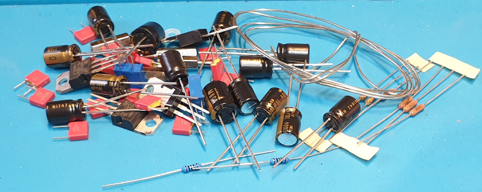
Part List
To give a clue about the number of parts and investment required hereby the list of my specific system.
Small parts like wiring, additional nut, bolts and some connectors are not on the list.
nr
description
subsystem
Supplier
count
price
total
1
DDDAC 1794 blue mainboard
dac
Audiocreative
1
€ 165,00
€ 165,00
2
DDDAC 1794 DAC board
dac
Audiocreative
2
€ 159,00
€ 318,00
3
DDDAC 12V PS
dac
Audiocreative
1
€ 94,00
€ 94,00
5
DIYINHK Ultra Low Noise PS
streamer
Diyinhk
1
€ 41,82
€ 41,82
6
Block RDK 30VA/2x6V
streamer
Conrad
1
€ 19,64
€ 19,64
7
Raspberry 3
streamer
SOSsolutions
1
€ 36,95
€ 36,95
8
SD Card 8 GB
streamer
SOSsolutions
1
€ 7,95
€ 7,95
9
Hifiberry Digi+ Pro
streamer
SOSsolutions
1
€ 42,95
€ 42,95
10
AC Main C14 Chassis part
case
Conrad
1
€ 5,25
€ 5,25
11
Fuse 20mm
case
Conrad
1
€ 1,20
€ 1,20
12
Torx147 Optical SPDIF Receiver 192k
case
Diyinhk
1
€ 3,35
€ 3,35
13
CinchConnector Rean AV NYS367-9
case
Conrad
1
€ 4,36
€ 4,36
14
CinchConnector Rean AV NYS367-2
case
Conrad
1
€ 4,36
€ 4,36
15
CinchConnector Rean AV NYS367-4
case
Conrad
3
€ 4,36
€ 13,08
16
Cinch-connector internal
case
Conrad
1
€ 1,48
€ 1,48
17
OLED Display 1.3″ I2C
case
Diymall by ebay
1
€ 8,51
€ 8,51
18
Galaxy Maggiorato GX388 330 x 280mm x 2HE 10mm front panel SILVER
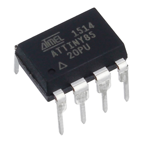
There is risk to corrupt the SD card of Raspberry Pi when it isn’t proper shutdown and I do power down my audio equipment when not in use. The Soft Power Off module, based on a ATtiny85, provides a solution for it.
There are some power down solutions for the Pi available, but none was suitable for my needs:
One button for power on and off.
Soft power down, that waits until the OS is also stopped.
Identification that the Pi is booting (blinking led)
identification that the Pi is shutting down (blinked led)
No power use when off, also no standby power.
The idea to use a small controller the ATtiny85 to manage the soft power control process. It controls a relay in combination with a double pole momentary switch. When the power switch is pressed one pole is used to bypass the relay, before the switch is released the controller is booted and activates the relay to ensure the power stays on.
At the same time the power LED in the switch start blinking and the Raspberry starts booting. After a while the Pi will toggle a GPIO pin to shows it is booted. In response the ATTiny stops blink the led and turns is on.
Soft power down circuit based on ATtiny85
When you power down by pressing the momentary switch again, the second pole is connected to the soft power down circuit. That delegates the power down request to the Raspberry Pi, and the LED in the switch starts blinking. When the Pi confirms the power down by toggling a GPIO pin to 0, the power circuit inactive the relay power relay.
When the Pi shutdown is initiated from the Pi is self, the same process is used. Only there is no blinking LED to provide feedback.
The process is shown in the following state machine:
Proof of Concept
Proof of concept is first created in with tinkercad , due it’s online a simulation, including with the programming of the tiny with Arduino.
tinkercad electronics with Arduino simulation.
Instead of a Pi a switch and LEDs are to simulate the sensor and actuators. After the successful Tinkercad test a breadboard is used for further testing.
Test board wiht the soft power down circuit.
During the testing on testing breadboard it was clear that Arduino bootlader is to slow. It would require that you hold the switch button for several seconds. After you remove the bootloader it boots in a blink, you will not notice it when pressing the button. The downside is that instead of cheap USB board, now you will need an In System Programmer. Fortunately you can transform an other Arduino, like an Uno, into an ISP .
The sketch is directly available in the Arduino IDE under examples with the name ArduinoISP.
Final Electronics
Finally we can build the real electronics. It exists out of an relay board with a controller on experimental PCB board next ot it. It’s on the to do list to create PCB to replace the relay and power down PCB, for now it’s good enough.
The schema and Tiny code can be found in my git repo with the dddac1794 build.
Raspberry Pi configuration
The solution provided here works of Raspberry with a OS derived from Raspbian Buster Lite 10.
To let the Raspberry Pi place nice with the soft power off module it requires 2 GPIO pins:
output pin; 1 is booted
input pin; 1 is request power off
In my system GPIO17 is used for the power state and GPIO22 for the request power off.
Of course we could write a little daemon for it, but the Raspberry hardware overlays already provide functionality for it.
The gpi-shutdown overlay provides a way to shutdown the Pi based on the toggle of an GPIO pin. And the overlay gpio-poweroff provide a way to show the current state with a GPIO pin.
If you add the following to lines to /boot/config.txt, after the next reboot this functionality will be active:
The power down request works fine. Only I don’t like that the power led stops blink direct after the start of the Pi. I would like that it stops blinking when the system is fully booted and ready to play music.
For that we needed to delay the activation of GPIO 17. Just using a cmd line command is attractive, but this gives problems with setting the power down state to 0. That should be as late as possible, preferable after the filesystem is umounted, which isn’t possible if you need to load command.
There is an alternative by loading the overlay ‘manually’. We just need to remove or comment the gpio-poweroff line in the /boot/config.txt and add a systemd service that loads the overlay instead.
Create a file in /home/pi with the name pipowerstate.service with the content: