During the a repair of an Amiga 2000 keyboard I didn’t found it very handy to use my Amiga as tester for a defect keyboard:
During testing, to prevent damage with unplug or plugin of the keyboard, it requires power down of the Amiga.Which takes a lot of time and proceedings (the boot, shutdown etc)
Change to damage the keyboard port of the Amiga if something was really wrong
So the idea began to take shape of we could build a simple tester. Next to me laying was a Arduino Uno with a Multi Functional Shield laying around. And the Amiga Keyboard protocol doesn’t seem to hard to me.
Hmmm lets first see if you one else already did use an Amiga Keyboard on an Arduino. And yes the is. The purpose of the solution in the thread, is using the Amiga keyboard on other computer with Arduino as USB adapter. I used the script provided in message #90 as basis. It is original written by Janne Lof, but I can’t find the original reference. You can find the modified Arduino sketch at :
The Arduino Uno doesn’t support using the device as an USB hid. So first get rid of the the USB code and use an Serial.print to test if it works. And then switch to use the 4x 7 segments display.
Amiga 2000/3000 pin out
Lets connect a suitable connector for my Amiga 2000 keyboards. See AMIGA Keyboard connector pin-outs for pin-out of the other models. Due the shield already taken a bunch of pins, we need other free pins to use. Preferred some that are already available on the unused headers on the shield.
#define PIN_KLCK 6 // black (was 8)
#define PIN_KDAT 5 // brown (was 9)
For testing we use serial port, after testing the serial code is disabled. In the Arduino IDE under the Tools menu is a serial monitor. In setupmake sure Serial.begin(9600);is called. Ok that seems to work. Now the script will be changed to:
Show the amiga (hex) keycode on the two first digits of the display.
On a key press the dp(=point) on the last segment will be on.
On a key release the dp(=point) on the last segment will be turned off again.
If an out of sync situation occurs the display show “____”.
In general it works well, but sometimes “____” or the key release doesn’t react. Lower the time of kdat low seems to improve it, but set to short, according to the protocol, some hardware will refuse to work it.
Some time ago I was offered a defective Amiga keyboard. It was Amiga 2000 Cherry Keyboard, one of the more rare Amiga 2000 keyboards. The previous owner informed me that the keyboard was not working at all.
This keyboard has several unique distinctive features:
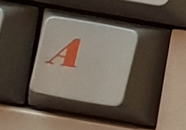
Red Amiga keys (notice different location of those keys; there is space between those keys and the space bar).
Uses Cherry MX switches.
Double shot caps (except for the Amiga keys); not printed symbols, but two colors of plastic. Just like my C64 keyboard.
Small function keys.
Let’s see how far we can get the keyboard working again.
First examination
An inspection of the exterior:
Plain label on the front with “Amiga 2000”
Slightly yellowed
No label of id on the bottom
US QWERTY layout
Nice red Amiga keys !
Big ass Return key
Six clickers for opening the case
Not the ergonomic connector seen with others, but I found pictures with exact the same connector and cable so it seems to be the original.
Foots the bottom are missing
In my opinion, the keyboard wobbles on the outer edges
It is opened before; the six clips looks scratched
After opening the case and inspecting the internals:
Identification:
On the PCB component side 4 labels:
879/00 11883 13047552 (white upper left corner)
Unreadable (orange above the F1/F2 keys)
197 (yellow above the F7/F8 keys)
Unreadable (white left from the cursor key > )
On the solder side of the PCB as part of the PCB: Cherry 601-1435 Rev.: 0.2
No metal plate to support the PCB and add a nice weight to the keyboard.
Old school lower quality pertinax PCB; the old brown stuff.
Damage to the traces and some pads
Normally on those two pads the shield cable is soldered.
Can be that there was to much mechanical stress and the traces came lose from the PCB.
The mask indicates that there should be 2 capacitors. But I’m not sure that it was ever there. Lets see if t can find photo’s of this area.
Due the damage above someone resoldered the shield cable
The solder looks no good.
It is connected to pin of a capacitor.
The trace did come loose from the pcb. (to hot welding temp used ?), so the capacitor is now floating.
Both pins pf the 6 MHz crystal looks to have bad solder joints. One is even loose.
PCB lacquer looks a little lumpy, nothing serious just aesthetic.
No other damage visible.
Some research
After some searching found that the PCB ID Cherry 601-1435 matches with Amiga Commodore G80-0879HAU (601-1435) Cherry MX Black. It looks like that this keyboard is only used for the first batch of Amigas A2000A r4.x (the German design) from 86/87. The USA based sites find it a rare keyboard, but I think in Europe it isn’t because the A2000A is never sold in the states. Nice article can be found on AmigaLove. On deskthority information and pictures are available.Based on one of that pictures:
It has the same cable and connector, so it it original. On AmigaLove it was stated that this keyboard has the ergonomic connector, but this isn’t always the case. The one on deskthority and mine obtained models have a different connector.
The pads (with the broken traces, on the images below the 4 holes right next to yellow wire) which are empty on my board are also empty on that picture, good news.
Image from deskthority.
It seems that the PCB from deskthority doesn’t have the brown pertinax PCB.
The keyboard controller is made out of one of the first Intel 8 bit micro controllers (MS48 family):
Intel P8049AH (from 1977!)
ET 2716 Q1 (EPROM) with version 467
74LS373
74HCT373
Crystal 6MHz
The good thing about this is; no special MOS chips involved. All later Amiga keyboards use a MOS keyboard controller. The P8049AH contains 2k ROM, it isn’t used and relies on an external EPROM for the program.
I’m not sure about it, but it looks that this keyboard PCB is produced by Cherry Germany and not Commodore. Cherry did use this controller logic with several of their other products. They used instead of P8049AH also P8039AH, which is the same model but without internal ROM. Are pin compatible and can de swapped. It is configured to use the external EPROM.
The repair attempt
Shield
Based on the damage found, I think that the ground is floating and not connected to the PCB. The damage is related to relocated and resoldered (with to much heat?) of the wire connected to shield carton. Lets first correct that by cleaning up add add a bridging wire and remove the shield wire.
Ok caps light will now turn on at startup, but further it is still dead. Remove the bridge wire again and provide are more permanent solution;
Desolder the bridge wire
Scrap the lacquer for 3mm from trace that is left, but unconnected. Clean it with IPA, followed by flux with heating.
Again clean with IPA and apply flux.
Finally apply solder to the fresh cleaned copper.
Measure the connection
If keyboard is working again restore the shield wire by an little bit more easy to handle wire and also solder it on an different location.
Crystal
Next in line are the bad solder joints on pad/pins of the crystal. Not clearly visible in the image, but both pins are loose in solder joints. Just reflow the joints. To be sure measure the crystal is still working check it with the scope. And the answer is no. Maybe are the bad joints related to the mounting method, it hings on the legs and provide mechanical stress to the joints. The crystal will be replaced and will get little support of a drop soft (removable) glue.
EPROM Check
Next I will check it the EPROM is this functioning. For this I need an ROM image to match it against. This ROM is part of the Mame emulator a2000kbd_g80_us device. Size and checksums are provided:
name
size
crc
sha1
467.u4
2048
fb92a773
e787dc05de227f30a47ac5b9ee7a355c2e9e693b
This source did only provided the checksums, but not the ROM it self. The checksums are just fine for verify that the content of the ROM is still ok, but I like to also have the image itself. Luckily the site retroroms provides all Mame roms including the a2000kbd_g80_us.zip rom.First check if the ROM matches the checksums provided above. I use the hex editor HxD for such things. Because the ICs on the keyboard PCB are soldered without sockets, I first have to desolder (so happy with my ZD-915 desoldering station !) the EPROM.
Now I can verify, using an old programmer Leap EP-1 with Windows 98 SE, if the content of the EPROM matches the ROM image. And yes it does.
The EPROM checks out to be ok!
New Shoes
Instead of soldering it back, I decide to first solder an DIL socket back. Normally maybe not wise for keyboard to have ICs in sockets, but it makes future repair, checks and replacements easier. And this keyboard will get an easier life that the previous 30 years, therefore I trust that the IC will remain in its socket. And while busy with the iron lets give the other ICs also some shoes 😉
Spare parts
To be prepared see if I can get replacement parts, if needed.T he two 74xxxxx can be obtained from normal electronics stores. The CPU and EPROM is different story. Luckily there is a company specialized in such parts and ask reasonable prices. This company is Slawmir in Poland (also present on ebay, use the filter “seller:slawmir” ). An used P8039AH CPU and an ET 2716 EPROM will cost less then €5, lets order it for just in case we need it.
Schematic
Lets check the traces again, this time not only optical but also with the multi-meter. To make sure everything is tested correct a schematic of the electronics would help, I could not find it only. Lets recreate an schematic with KiCad. The PCB is self and the MCS-48 Family User’s manual are used to create the scheme. Is fairly basic setup:
Timing circuit .
Reset circuit.
Extern EPROM with latch for the lowest 8 bits.
Additional 8 inputs with a HCT373.
Use port P1 and part of port P2 for IO.
The kclock and kdata use both two pins; one output and an interrupt input.
The only tricky one is the reuse of the for lowest bits of P2 for both address and IO.
Now we have a schematic, additional I will also create the PCB layout with only component placement (no traces):
Both together make it very efficient to measure the connections without constant following the trace. And because the ICs already have sockets, let get the IC’s out to make the measurement even more easy and have no risk at damaging the old ICs.Just following the connection from pin to pin in the scheme to see if it works. Also check for double connections.
Trace Connections
We start with measuring only the area where the control electronics are, not the connection of every Cherry MX switch. I only will follow a few of those just see if at least one switch and its connections are correct. After measuring with the multimeter at least the A8 and A9 signal seems not connected to the EPROM. Finally with an inspection with 8x zoom showed very thin crack in the upper layer of the underside of the PCB.The crack is spread over 6 traces, one affected (A10) is still working. Clearly I need some better tooling for visual inspection.
Restore A8 & A9
First quick fix is to temporary add some bridge wires for A8 and A9 to see if this is the last error to fix. Boot with AmigaTestKit (formerly SysTest) And yes it works! Only the O and Z aren’t working, probably due the other broken traces (checked the switches).
Remove the coating from the damaged traces and cleanup with IPA and flux.
Then apply flux and with a very small soldering tip apply some tin on it. Steady hand required each trace is less then a 0.4 mm width.
And after soldering each broken trace all keys work again.Finish this with a strong lacquer to seal it.
Cleaning and put it back together again
Time to clean the enclosure and keys. All keys are removed and cleaned piece by pieces.
Now the keys are removed, you can seen that it are really double shot keys; no printed symbols, but used two different colors of plastic. This guarantees that the colors will not fade in time or use. Only the Amiga keys are an exception, those are still printed. All A2K,A3K,A4K keyboards that come after this model all have printed symbols.
Hmm I don’t like the way the spacebar is moving. It seems that one guidance of the stabilizer is broken.
Use some power glue to restore it and add some soft (removable) glue to outside to provide some support.
Due the clips of the enclosure closing and the the tight space for the keyboard cable, I use the following order for putting the enclosure back:
Take the upper part of the enclosure.
Place it up side down.
Place the PCB.
Make sure the keyboard cable is placed correct .
Place the two internal screws, but not fully tight them.
Move the PCB to most up.
Now you can tight both the screw.
Take the lower part of the enclosure
Place it up side down
Place the shield (with metal folly to the plastic)
Fix it with some tape or fold the folly in place with your hand
Now you can place both together and press the clips
And the end result:
Bonus
Because the schematic and PCB layout are created in KiCad, we also now have a nice render of the PCB. Including identification of the problems areas. Each of the three areas was enough to make the keyboard not work. This is the first I had to repair something with a triple error with the same effect; a dead keyboard.


