moOde with USB input

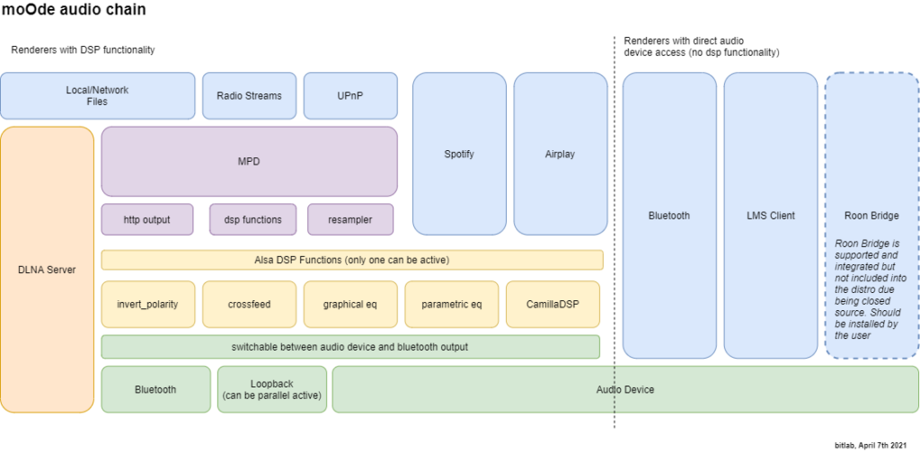
moOde supports various audio sources. The most common used sources are (network) files and streaming (UPnP/Airplay/Bluetooth). Also alternative renders like Roon and LMS are available. But what if you want to capture external source like SPDIF or analog?

Maybe you just want to select you source digital, or stream it over the air or you just want to apply CamillaDSP to everything you play. Currently this isn’t supported out of the box with moOde. Luckily it can be accomplished with very small effort.

What will we do?

Sorry but this is going to be a long read:

  1. First we will collect some info about the available audio inputs.
  2. Next make a configuration which make dealing with the inputs easier.
  3. The main dish; how to use the inputs in a little bit fancier way with MPD/moOde.
  4. And for the hardcore audience; as dessert followed by an how to use the inputs with CamillaDSP directly.

None of the activities involves programming or changing code of moOde. Just changing setting and creating/update some configuration files.

Because we concentrate on the inputs this time, I assume that you already have setup a working audio output on your Pi with moOde. (At the moment of writing moOde 8.0.2 is used). And checked that CamillaDSP flat config works fine.

The used device

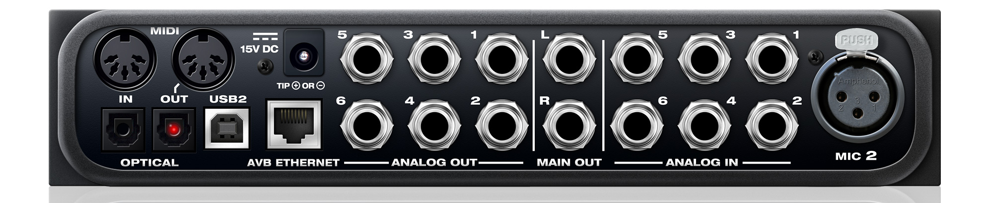
As example device we will use a MOTO AVB device, with the following input mapping:

  • analog 1 input (device channels 0,1)
  • analog 2 input (device channels 2,3)
  • analog 3 input (device channels 4,5)
  • toslink (device channels 6,7)

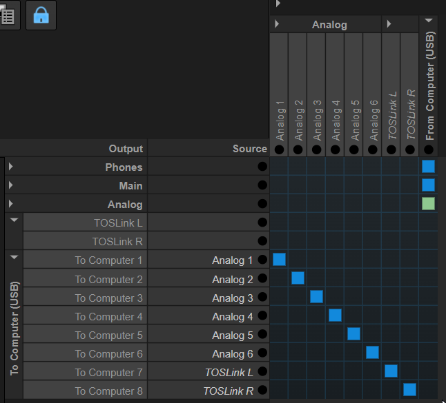
This mapping will differ per used device, with most MOTU devices you can setup a mapping in the settings of the device:

Used MOTU Routing table

Disclaimer: I’m using this device because this is what I have at hand. It’s a fantastic device for what I normally use it for. But in the context of this blog, inputs, it (or the drivers) has some quirks. The UAC compatibility is not straight forward. And yes I also tried the Drumfix drivers from github. If you’re interested I have a prebuilt debian package for moOde available.

Device details

Before we start configuring the system, we need some details about the device. The same tools can also come in handy when solving problems.

List available usb devices

pi@moode:~ $ lsusb -tv
/:  Bus 02.Port 1: Dev 1, Class=root_hub, Driver=xhci_hcd/4p, 5000M
    ID 1d6b:0003 Linux Foundation 3.0 root hub
/:  Bus 01.Port 1: Dev 1, Class=root_hub, Driver=xhci_hcd/1p, 480M
    ID 1d6b:0002 Linux Foundation 2.0 root hub
    |__ Port 1: Dev 2, If 0, Class=Hub, Driver=hub/4p, 480M
        ID 2109:3431 VIA Labs, Inc. Hub
        |__ Port 1: Dev 3, If 0, Class=Audio, Driver=snd-usb-audio, 480M
            ID 07fd:0005 Mark of the Unicorn
        |__ Port 1: Dev 3, If 1, Class=Audio, Driver=snd-usb-audio, 480M
            ID 07fd:0005 Mark of the Unicorn
        |__ Port 1: Dev 3, If 2, Class=Audio, Driver=snd-usb-audio, 480M
            ID 07fd:0005 Mark of the Unicorn
        |__ Port 1: Dev 3, If 3, Class=Audio, Driver=snd-usb-audio, 480M
            ID 07fd:0005 Mark of the Unicorn
        |__ Port 1: Dev 3, If 4, Class=Audio, Driver=snd-usb-audio, 480M
            ID 07fd:0005 Mark of the Unicorn
        |__ Port 1: Dev 3, If 5, Class=Vendor Specific Class, Driver=, 480M
            ID 07fd:0005 Mark of the Unicorn
        |__ Port 1: Dev 3, If 6, Class=Vendor Specific Class, Driver=, 480M
            ID 07fd:0005 Mark of the Unicorn
        |__ Port 1: Dev 3, If 7, Class=Vendor Specific Class, Driver=, 480M
            ID 07fd:0005 Mark of the Unicorn

Notice the Class=audio with the Driver=snd-usb-audio (or motu when using the drumfix drivers); that is a UAC comptabile interface.

List the available capture devices

Lets see which capture devices are available with Alsa:

pi@moode:~ $ arecord -l
**** List of CAPTURE Hardware Devices ****
card 2: AVB [UltraLite AVB], device 0: USB Audio [USB Audio]
  Subdevices: 1/1
  Subdevice #0: subdevice #0

From this output we learned that the capture device has card number 2.

Get details of the capture device

Now we know the card number we can dive deeper for more details:

pi@moode:~ $ arecord -D hw:2,0,0 --dump-hw-params
Recording WAVE 'stdin' : Unsigned 8 bit, Rate 8000 Hz, Mono
HW Params of device "hw:2,0,0":
--------------------
ACCESS:  MMAP_INTERLEAVED RW_INTERLEAVED
FORMAT:  S24_3LE
SUBFORMAT:  STD
SAMPLE_BITS: 24
FRAME_BITS: 576
CHANNELS: 24
RATE: [44100 192000]
PERIOD_TIME: [125 165103)
PERIOD_SIZE: [6 7281]
PERIOD_BYTES: [432 524232]
PERIODS: [2 1024]
BUFFER_TIME: (62 330227)
BUFFER_SIZE: [12 14563]
BUFFER_BYTES: [864 1048536]
TICK_TIME: ALL
--------------------

This time we learned:

  • The sample format of the device is S24_3LE.
  • It haves 24 input channels available.
  • Is supports a sample rate from 44.1kHz till 192kHz.

Splitting the inputs

To make it easier to select the correct input, you can split up the input. Nice background article about how to do that is Audio multi-channel routing and mixing using alsalib.

For this we will create a file /etc/alsa/conf.d/motu_avb_inputs.conf, with the content below.
The name of the file can be anything, as long as it is put in the correct location.

pcm_slave.motu {
        pcm "hw:2,0,0"
        rate 44100
        channels 24
}

pcm.ainput1 {
        type dsnoop
        ipc_key 12378
        slave motu
        bindings.0 0
        bindings.1 1
}

pcm.ainput2 {
        type dsnoop
        ipc_key 12378
        slave motu
        bindings.0 2
        bindings.1 3
}

pcm.ainput3 {
        type dsnoop
        ipc_key 12378
        slave motu
        bindings.0 4
        bindings.1 5
}


pcm.toslink {
        type dsnoop
        ipc_key 12378
        slave motu
        bindings.0 6
        bindings.1 7
}

If you copied the new configuration file to the correct location, you can check the availabity of the new named input devices

pi@moode:~ $ arecord -L
...
ainput1
ainput2
ainput3
toslink
...

Next you can optional test if you can record from a specific input:

pi@moode:~ $ sudo arecord -D ainput1 -f S24_3LE -r 44100 -c 2 test.wav

(ctr+c will abort the recording)

And if you want to play it back (of course use your own device here):

aplay -D plughw:2,0 test.wav

If you came this far for own device, you will have now a working input(s). Next is to simultaneous capture and play it back.

Using inputs with MPD and the moOde user interface

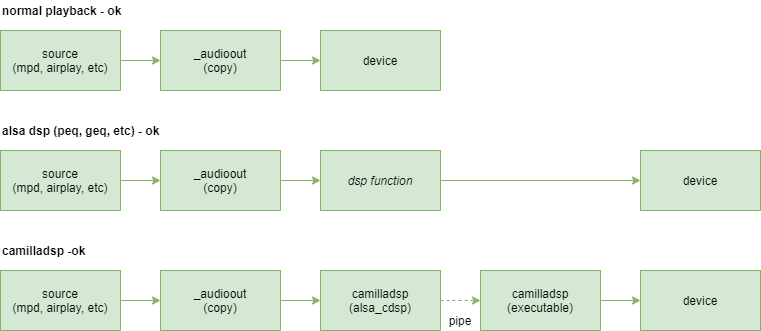
In this mode the audio input is captured by MPD before handing over to CamillaDSP or audio device.
This is as simple as creating a playlist with the inputs mapping of above :

#ETM3U

#EXTINF:-1, input 1
alsa://plug:ainput1?format=44100:24:2
#EXTINF:-1, input 2
alsa://plug:ainput2?format=44100:24:2
#EXTINF:-1, input 3
alsa://plug:ainput3?format=44100:24:2
#EXTINF:-1, toslink
alsa://plug:toslink?format=44100:24:2

Place this file in the playlist directory of your moOde system:

  • By using the network share \\<moode host name or ip>\Playlists
  • Or place it directly local on the moode system at the location /var/lib/mpd/playlists/.

In this case I named it motu.m3u.

Unfortunately the EXT information isn’t shown by MPD. It would nicer if the EXT info name was shown instead of the full alsa plugin config.

If it is possible to use the EXTINF, please let me know.

You can find back the playlist in library view of moOde:

Library view of moOde
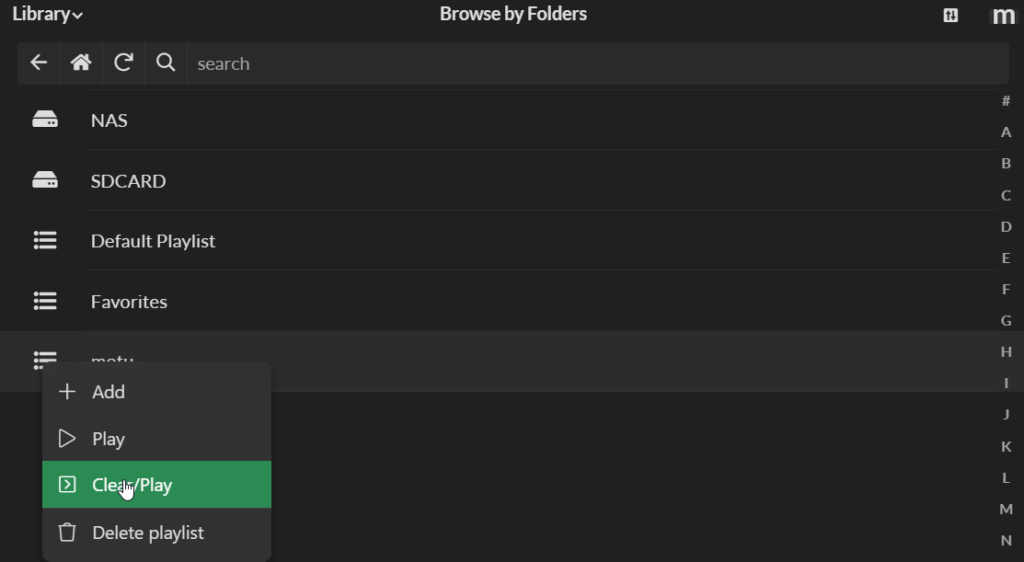
  • Press on hamburger menu left from playlist name
  • And press Add, Play or Clear/Play

Now the playlist is active of the main screen. You can select a different input by click it on in the current playqueue.

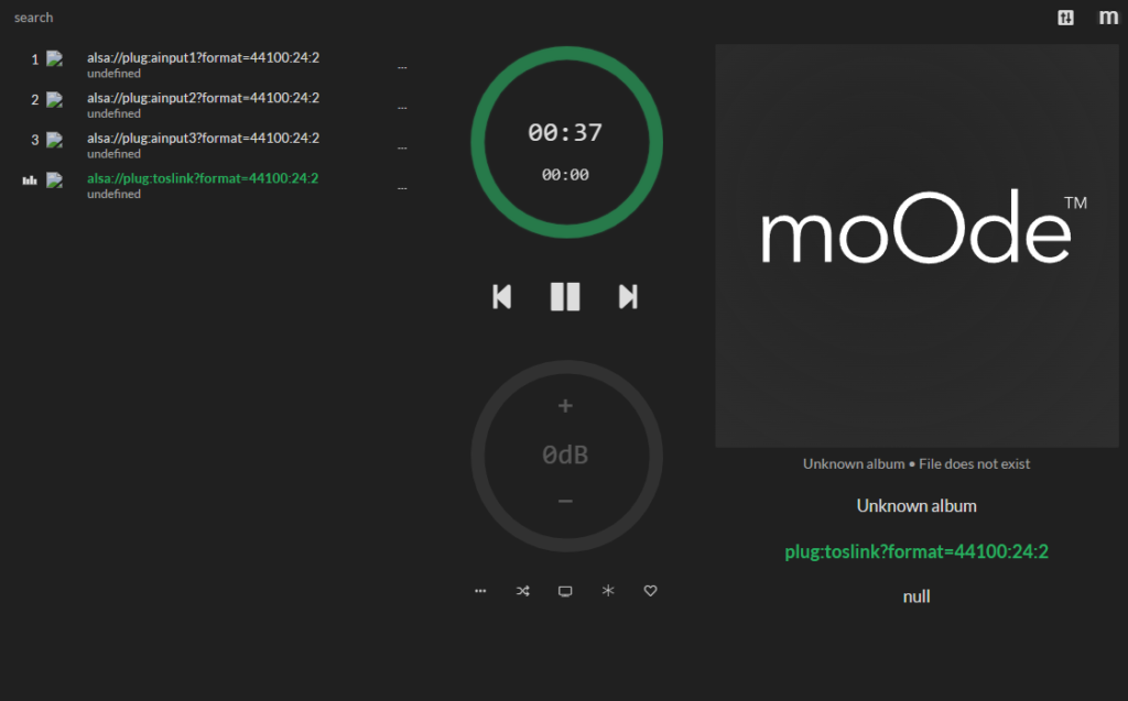
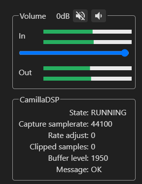
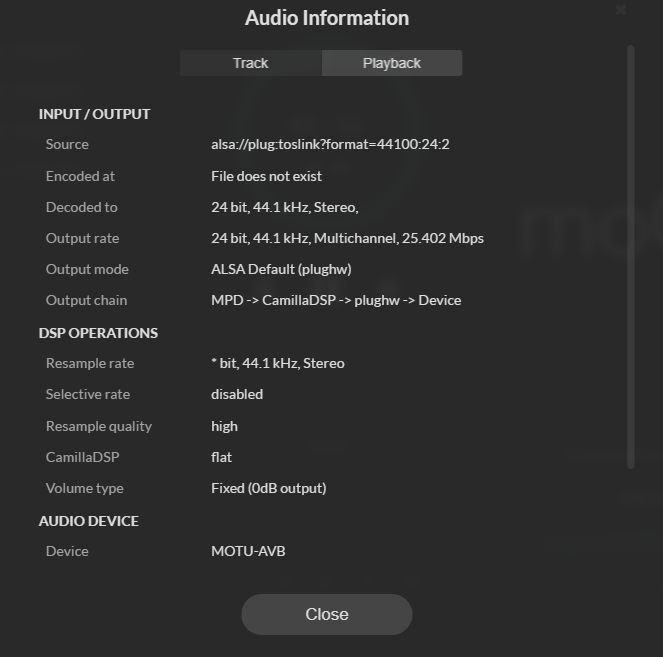
And of course proof that it is playing as expect from the audio information dialog (press the M in the upper right corner and select audio info):

audio information of selected input source

Below is a screenshot with the CPU load of simultaneous capture and playback on a Pi 4:

CPU load simultaneous capture and playback

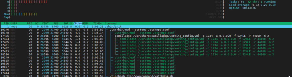
Despite the fact that the input selection is not fully integrated in moOde, that wasn’t so hard to do. I think we come a long way with the playlist.

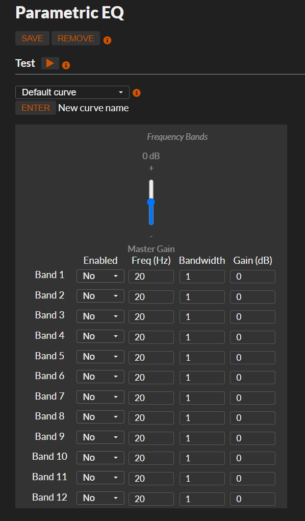
Any DSP function like the Peq or CamillaDSP can be applied just like with regular MPD playback.

Using the inputs directly with CamillaDSP

This chapter isn’t needed unless you want to bypass MPD between the capture input and CamillaDSP. But it will be less flexible than the MPD solution.

If you just want to directly use the source with CamillaDSP you can arrange this from the CamillaDSP configuration file.

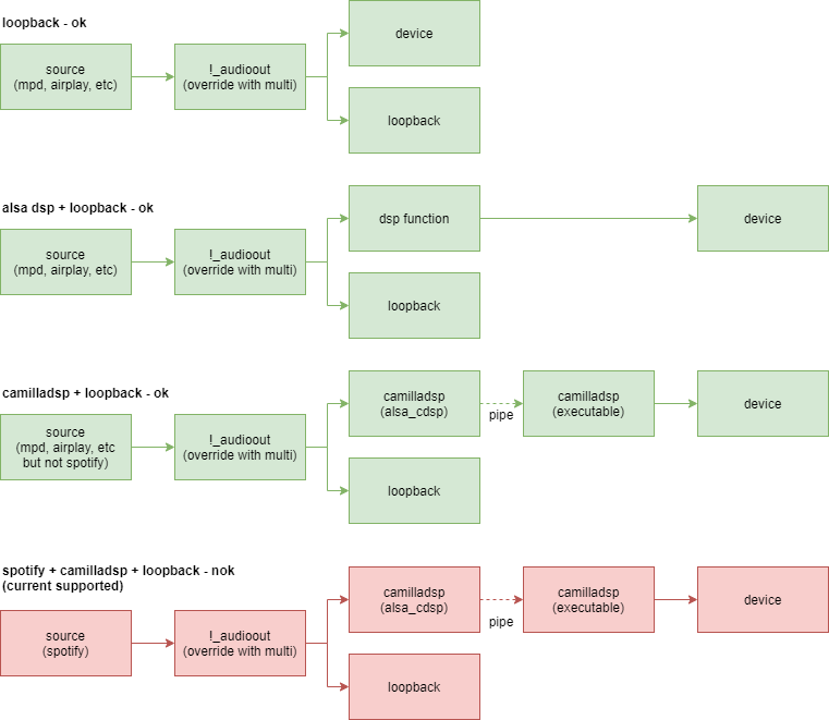
Only the default configuration of CamillaDSP with moOde doesn’t allow using the inputs from the CamillaDSP configuration file. This is because moOde is using the great alsa_cdsp module from scripple. This module makes automatic rate, format and channel switching possible with CamillaDSP.

But when alsa_cdsp is used alsa_cdsp also is in control of starting and stopping CamillaDSP, which is required when changing rate, format or channels.

To use the inputs directly with CamillaDSP we need to:

Downside is that as long as CamillaDSP standalone is used the output device, no other device can use the output device directly.

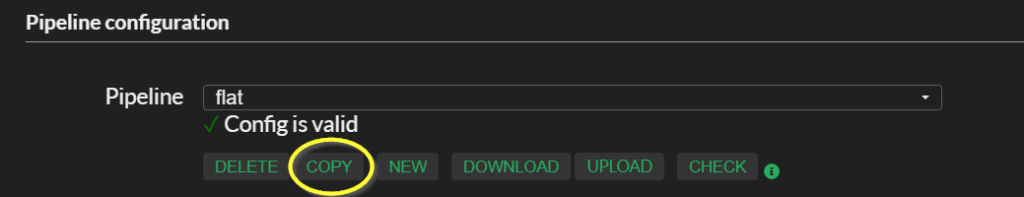
Copy a clean config:

  • Select the configuration flat
  • Press copy
  • Named it cdsp_direct
Copy config

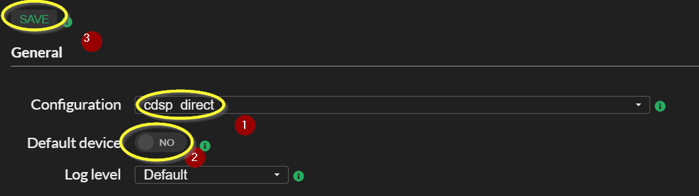
Make it the active configuration:

  • Select if as the active config
  • Make sure default device is turned ON
  • Press save
  • Toggle default device OFF
  • Press save again
Set active config

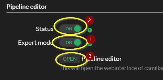
Open the CamillaDSP pipeline editor:

  • Toggle Expert mode to ON
  • Toggle Status to ON
  • Press OPEN
Open the pipeline editor

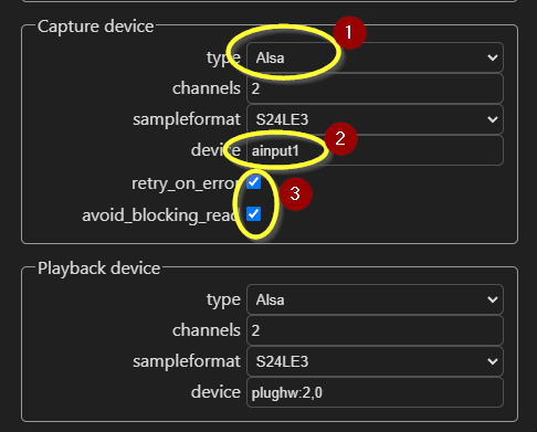
Set the capture device

  • Change the capture device to alsa
  • Set as device the desired input, in my case ainput1
  • Step 3 is optional

Start CamillaDSP standalone

Login to the terminal (with SSH or the onboard webterminal from moOde in system config)

Type in the following commands:

pi@moode:~ $ mpc stop
pi@moode:~ $ wget https://raw.githubusercontent.com/moode-player/pkgbuild/main/packages/camilladsp/camilladsp.service
pi@moode:~ $ sudo mv ./camilladsp.service /lib/systemd/system
pi@moode:~ $ sudo systemctl start camilladsp
pi@moode:~ $ sudo systemctl status camilladsp

If you are happy with the result, after testing, you can the command below to make sure CamillaDSP is started again after a boot:

pi@moode:~ $ sudo systemctl enable camilladsp

If you play music at input source, you should be able to see it at the volume bar in the pipeline editor:

moOde backup & restore

With moOde version 7.4 comes a system backup & restore. This article provide some details about the backup/restore.
Luckly moOde 7.4 comes , besides an full image, also as an update for existing 7.3 systems.

  • The backup mananger can be used in the following scenario’s:
  • Backup and restore to the same moOde version.
  • Backup and restore to a new moOde version.
  • Backup and restore to a new moOde version.
  • Backup and restore to an older moOde version.

All source and target systems should run at least 7.4 or higher.

When restoring to a different version, no supported settings will be dropped.
Restoring to an older version is supported as long as it will not take development effort to support it.

Backup content
What does a backup contains:

  • system configuration
  • radio stations
  • camilladsp configuration and ir files
  • if used background image

The same system configuration as with autocfg is supported. Practical that means a lot of settings are supported, but not all yet.

Camilladsp configuration files are restored, but in case of breaking format changes not automatically upgraded. Keep an eye on the changelog of the camilladsp project it self.

Where to find the backup & restore tools?

On System Config page a backup/restore section is present to start the backup or restore dialog.

backup and restore section

How to create a backup

On the backup page several options are available. When your system runs on WiFi a WiFi password needs to be provided.

To support customomazations out of the box an optional a script can be provided that will be executed on restore.

The radio stations exists out of the the system defined ones (moOde) and use defined ones (called Other in moOde).
If you want to save some space, you could leave the system defined ones out of the backup.

Backup options

After your press the create backup button a zip file will be downloaded with the backup.

Restoring a backup

There are two ways to restore an backup:

  • Through the graphical user interface in the browser
  • Restoring a backup on the initial boot of a system

Through the web GUI

  • Go the System Config page and press the restore button.
  • Press select backup file and upload a backup
Restore options
  • Only the option present in the backup are enabled. You can still disable the restore of parts that are present in the backup.
  • As last step press the Start Restore button.

If the restore also restores the system configuration settings, automatically the system will reboot twice. It can take a few minutes to complete. Probably you will have to refresh/reload browser manually.

Through the initial boot

This is an easy way to restore backup of reconfigure systems on (initial) boot. Downside is that there is no way to select what to restore from the backup. Make sure the backup contains only the parts you want to restore. For example leave out the system defined radio stations.

Usage:

After burning a fresh SDCard, simply place the backup in the boot partition with the name moodebackup.zip.

For the brave

The backup / restore is based on a number of commandline tools which also can be called directly from commandline.

Especially the radio station backup restore have extended options.

The tools are:

  • moodeutl – for generating autocfg settings
  • stationmanager.py – system backup files are compatible with stationmanager.py
  • backupmanager.py – used both moodeutl and stationmanager.py

The tools contain command line help with -h|--help.

moOde 7.3 audio infrastructure

The moOde audio player contains a very rich features set. This article describes the audio infrastructure of moOde as per version 7.3. It show the general audio parts involved and an overview of the ALSA configurations.

moOde is fully GPL 3 based and only uses free available open source software. Shady origins of sources/packages are not used. The maintainer Tim Curtis is very strict on this, which is good thing.

Consequence is that for example some popular streaming service are not native available and only can be used by using something in the middle like UPnP Bubble and UPnP.

The image below shows an birdseye overview of the audio infrastructure:

moOdes audio chain

This is the infrastructure as moOde is configured and doesn’t necessarily relate to the all possibilities of the specific application or the entire chain in general.

When you select an audio device on the moOde configuration audio or MPD page, moOde update the configuration of all sources to use the correct device.

The blue blocks are possible audio sources. The first three source are inputs to MPD and have the most rich features. Second best are Spotify and Airplay. Bluetooth, LMS Client and Roon Bridge, can only be used the configured audio device, moOde doesn’t provide any DSP options for those. LMS an Roon provide there own DSP functions.

The following alsa dsp functions are available:

  • invert polarity
  • crossfeed with several modes available
  • 10 bands graphical EQ (Alsaequal)
  • 12 bands parameteric EQ (custom 12 bands based on caps EqFa4p).
  • CamillaDSP very flexible audio processing (think of EqualizerAPO but then for Linux)

When applying an alsa dsp plugin you can only choose one dsp function a time to be active. If you need a combination CamillaDSP is your friend.

In addition if your source is MPD related, first three input, you have also a powerful soxr resampler in MPD at your disposal. Including selective resampling and custom recipes.

Alsa audio path

moOde makes use of the Advanced Linux Sound Architecture (ALSA) for audio playback. The diagrams below provide an overview of the path audio has to take from source to device.

alsa configuration

The default the is to use alsa plughw to access a device. Plughw provides automatic, if needed, samplerate and bitdepth conversion. For example if Airplay provides 16 bit and your device expect 32bit, this would result without conversion in an playback error.

For the purist among us it also possible to use the direct mode (under alsa options at audio configuration page). In the case alsa hw is used to access the devices. This ensures no changes to the audio stream are made, but can result in audio device output errors.

Note: The direct (hw) option is only available for the first and last one configuration.

Loopback

moOde also support splitting the audio with a loopback. The output of the loopback device is intended to be used for visualization extensions.
Below are the alsa configuration provided with the loopback on. In this case alsa plughw is always used, mainly to correct bitdepth when required. Notice that the last configuration isn’t supported for now.

alsa configuration with loopback


We reached the end of the article and I hope you now have a better picture about how the moOde audio infrastructure is working.

Using Camilladsp with moOde 7

Update: The upcoming moOde version 7.1 will have improved integration. See Using Camilladsp with moOde 7 – Part 2 .

Camilladsp is audio processor with both FIR and IIR filters, written by Henrik Enquist. Despite Camilladsp is not, yet, integrated in to moOde, it supplies Camilladsp version 0.4.0 to experiment with. This article shows you how.

To integrate MPD with Camilladsp @scripple created an alsa plugin based bluealsa called alsa_cdsp. This module alsa handle switching the audio format for Camilladsp. Also this module is already included in moOde 7.

Also default configuration files are supplied :

  • /usr/share/camilladsp/config.out.yaml (default camilladsp config used by alsa_cdsp for camilladsp)
  • /usr/share/camilladsp/config.yaml
  • /etc/alsa/conf.d/camilladsp.conf (for the alsa_cdsp module)

Before you continue make sure moOde functions correct and can playback audio of the correct audio device. Required is that you are familiar with the SSH terminal and editing configuration files on the moOde file system.

What do you need to your self to make it work

  1. Assign the correct output device to camilladsp.
  2. Make the alsa_cdsp as output available with moOde/MPD.
  3. Edit the camilladsp to contain you own filter pipeline.

Set output device to camilladsp

We assume that you want to apply camilladsp to the same output device as used for moOde, but these can of course also be completely different devices and even several devices.

Normally if you select an output device moOde will update the configuration alsa files. For camilladsp we have to do it our selfs.

First find the current used device:

pi@moode:~ $cat /etc/alsa/conf.d/alsaequal.conf | grep plughw
slave.pcm "plughw:2,0";

Is this case it concerns the device hw:2,0, notice not plughw.

Next is to used the same device as playback device in camilladsp.
Open the /usr/share/camilladsp/config.out.yaml (in case alsa_cdsp is in the mode config_cdsp 1, else use the config.yaml variant), in your favorite editor .

Replace the playback device by correct one, just like in this example hw:2,0.

devices:
  samplerate: 44100
  chunksize: 1024
  queuelimit: 1
  capture:
    type: File
    channels: 2
    filename: "/dev/stdin"
    format: S16LE
    extra_samples: 8192
  playback:
    type: Alsa
    channels: 2
    device: "hw:2,0"
    format: S32LE
~

Route the audio to the camilladsp

Because camilladsp isn’t integrated yet in moOde and we don’t want to edit the moOde code we have to hijack an existing MPD output.

You can see the available outputs with:

pi@moode:~ $ mpc outputs
Output 1 (ALSA default) is enabled
        allowed_formats=""
        dop="0"
Output 2 (ALSA crossfeed) is disabled
        allowed_formats=""
        dop="0"
Output 3 (ALSA parametric eq) is disabled
        allowed_formats=""
        dop="0"
Output 4 (ALSA graphic eq) is disabled
        allowed_formats=""
        dop="0"
Output 5 (ALSA polarity inversion) is disabled
        allowed_formats=""
        dop="0"
Output 6 (ALSA bluetooth) is disabled
        allowed_formats=""
        dop="0"
Output 7 (HTTP stream) is disabled
 

Lets reuse the ALSA graphic output for camilladsp.

That output is defined in the /etc/mpd.conf:

audio_output {
type "alsa"
name "ALSA graphic eq"
device "alsaequal"
mixer_type "software"
dop "no"
}

We need to change the device form “alsaequal” to “camilladsp”. Only editing the file directly isn’t a great idea, because the file is is generated by moOde.

Luckily moOde provide a way where custom mpd configurations can be merged with the moode mpd configuration.

First create a custom mpd configuration file called /etc/mpd.custom.conf. Put the following content in it:

audio_output {
name "ALSA graphic eq"
device "camilladsp"
} 

This will make sure the device name of the audio output with the name “ALSA graphic eq: is replaced.

If the moOde 7.0.0 image the alsa_cdsp module is in the wrong place (my bad) !!!
You have to correct that by running the following command:

sudo install -m 644 `pkg-config --variable=libdir alsa`/libasound_module_pcm_cdsp.so `pkg-config --variable=libdir alsa`/alsa-lib/

Next enable the mpd custom configuration support by running the following command and restart moOde:

moodeutl -A add 32768
moodeutl -r

Final step to activate the output is in the moOde configuration interface. Go to the audio configuration page select a Graphic EQ curve and press SET:

You check this with:

pi@moodep4:~ $ mpc outputs
Output 1 (ALSA default) is disabled
        allowed_formats=""
        dop="0"
Output 2 (ALSA crossfeed) is disabled
        allowed_formats=""
        dop="0"
Output 3 (ALSA parametric eq) is disabled
        allowed_formats=""
        dop="0"
Output 4 (ALSA graphic eq) is enabled
        allowed_formats=""
        dop="0"
Output 5 (ALSA polarity inversion) is disabled
        allowed_formats=""
        dop="0"
Output 6 (ALSA bluetooth) is disabled
        allowed_formats=""
        dop="0"
Output 7 (HTTP stream) is disabled

If everything went well output 4 is active.

Editing the camilladsp configuration

Maybe one day if moOde fully integrate camilladsp including the camilladsp web gui, you will have a fancy configuration editor, but for now you have to do it your self.

Open the /usr/share/camilladsp/config.out.yaml (in case alsa_cdsp is in the mode config_cdsp 1, else use the config.yaml variant), in your favorite editor . And edit it to your wishes, see the camilladsp documentation for more.

After configuration restart moOde with moodeutl -r. Alternative stop your audio stream with the command mpc stop and enable it again mpc play.

If you prefer to upload a configuration file instead , please don’t forget to set the correct output device.

DDDAC 1794 Build – Part 2

In the article DDDAC 1794 Build I describe my personal build of the DDDAC1794 NOS DIY DAC. Because it is a DIY project it is always on the move. Part 2 contains the updates since the previous article.

Changes are:

  • Add third DAC Module PBT
  • Used a LT3045 from LDOVR to replace the LF50 on the mainboard.
  • Power Distribution PCB
  • Used Ian Canada FifoPi Q3 to replace the combo Hifiberry Digi+ Pro and Allo Isolator.

The schematics and tweaks of the previous build are archived on in my Github repo under the tag build_hf_alloisolator.

Third DAC Modules PBT

With a third DAC module the maximum capacity is reached in my enclosure.

As always Audio Creative delivers fast and complete. Soldering only requires through-hole components so it is easy to do.

Within 30 minutes the DAC board is finished.

Just put this on the top one existing one.. Instead replacing the silver wire of the already existing boards, I just solder the silver wires with silver solder to top of the existing connections.

Next the value of the V/I Rload resistors needs to be correct. The value is 134Ω divided by the number of boards. For the 2 boards boards 68Ω is already used in place. Just putting a 133Ω in parallel with it will make an Rload of 45Ω.

After power the leds of the onboard tent regulator turn on so it looks like the mission succeed.

Next is calibration of trimmers. Both need to be adjust to 40mV on the test point. Which the voltage between the leg of the resistor next to the trimmer and common.

LT3045

The LT3045 from LDOVR is a 78xx/LFxx pin compatible power regulator.

Ultra Low Noise Low Dropout Voltage Regulator, 78XX replacement

We gonna use this regulator to replace the mainboard 5V regulator. There it is used to feed the logic for the I2S delayline, buffer and I2S/SPDIF selector. The SPDIF electronics and Tent clock are fed by separate regulators.

To fit the LT3045 you first have to desolder you current LF50, it sit just next to power terminal of the mainboard.

AC Power Distribution PCB

To cleanup the wiring for the power distribution and remove the current relay board, I created a small PCB. You can read about it in article below:

FifoPi Q3

FifoPi Q3

Apart from the hopefully soundwise improvements, replace the Hifiberry + Isolator with the FifoPi also reduces the building complexity a little bit:

  • Normal size screw terminals for the dirty and clean power.
  • Isolated and non isolated GPIO header, no need a GPIO for breakout between the Pi and Isolator anymore.
  • Nice F.UL connector for the I2S signals.

Downside is that the FifoPi form factor isn’t exactly the size of a regular Pi hat. Especially on the side of the SD card makes this it harder to replace you SD card.

The new FifoPi has stripped the LDO regulators from the PCB to allow your own PS solutions. The isolated part requires a clean 3.3V.

Th e DIYIHNK 4.7uV Ultra low noise regulator.

The voltage regulator I used to feed the Allo Isolator was a DIYHNK 4.7uV ultra low noise regulator based on a TPS7A4700. Luckily the TPS7A4700 is a programmable regulator and default a jumper is present to select between 5V and 3.3V. Other voltages can be made by adding jumpers to the available solder pads.

For connecting the I2S with F.UL connectors I ordered three (MCLK isn’t used) 6″ premade cables. Each cable contains a signal and GND as shield. On one side just cut of the connectors added a header for the I2S connector.

Because the power supplies between the FifoPi and the DDDAC are completely separated, it also requires that the ground is connected. By using the shield of one of the F.UL cables this is a very clean solution, very small GND path. In the image above this the white/green wire.

Use some hot glue to provide some additional support to the wires.

As probably known I’m moOde fan, which uses a regular Linux kernel for the Raspberry Pi. The used driver for FifoPi is the generic rpi-dac, which is actually for a PCM1794 (talking about coincidence ). Only the codec of this driver has a software limit of 192kHz, while the Pi supports 384kHz and also the FifoPi/ DDDAC1794.

I have created a small patch to increase the max frequency to 384kHz in the article below:

Updated schematics

All updated schematics can be found in the matching github repo https://github.com/bitkeeper/dddac1794build.

For completeness below are the updated schematics shown:

The blocks:

The logical connections:

And the electronic schematics:

We reached the end of the changes to the build. And maybe Santa send me some clock upgrades for the FifoPo …

For now, it is time to enjoy listening to music again!

moOde with AutoEq headphone equalizing

2020-10-29: The new 12 band parametric Eq will be part of of the upcoming moOde 7.0.0 release

The AutoEq project provides headphone equalize settings. The equalizing requires at least a 5 band parametric equalizer and would prefer a 10 bands for optimal results. Standard moOde only provide a fourfold parametric equalizer.

The used parametric equalizer in moOde is the EqFa4p from the CAPs project.

Quoted from the caps website:

Four Mitra-Regalia peaking equaliser filters in series; a vector arithmetic re-implementation of Fons Adriaensens “Parametric1” equaliser[fafil] with minor differences. 
Parallelisation of the serial filter organisation causes the output to lag by three samples.

With playback the output lag isn’t a concern, I have created a version of the equalizer with 3 x 4 parallel filters.

By lack of an official repo to fork from, I put the latest 0.9.26 source from the caps website im my own Github repo at bitkeeper/caps . The branch eqfa12p_12_band_parametric_eq contains a caps version with an EqFa120p.

Ok technical the name should EqFa3x4p and not 12p, but for now it is EqFa12p.

Getting, build and installing the new caps library

git clone --single-branch --branch features/eqfa12p_12_band_parametric_eq  https://github.com/bitkeeper/caps.git
cd caps
./configure.py
make
sudo make install

Let moOde use the EqFa12p

First to allow alsa to find the new filter we have to register the plugin by creating (requires sudo) a file called /etc/alsa/conf.d/eqfa12p.conf with the following content:

pcm.eqfa12p {
    type plug
    slave.pcm "plug_eqfa12p"
}

pcm.plug_eqfa12p {
    type ladspa
        slave.pcm "plughw:2,0";
    path "/usr/lib/ladspa";
    plugins [ {
                id 2611
                label EqFA12p
                input {
                    controls [1 14 1.471 6.0  1 1365 1.282 10.4  1 3212 0.442 5.6  1 4600 10.000 -9.5  1 11179 0.510 11.5  1 4572 0.110 3.1  1 6779 0.265 -4.6  1 8996 0.193 5.0  1 11627 0.175 -2.6  1 15559 0.276 2.1   0 20 1 0  0 20 1 0  -6.5]                       
                }
    } ]
}

The line that start with controls (all values should be on one single line) contains the setttings exactly the same as with the EqFa4p; per band enable/disable, frequency,bandwidth and gain. Add the end single which is the overall gain. In the example are the setting for my Sennheisser HD800S used.

Mostly with parametric eqs the Q is used instead of bandwidth parameter. The filter bandwidth factor could normally be calculatedby deviding the center frequency by the Q factor. Only it doesn’t seems to be correct with EqFa.

After reading the excellent article Parametric Equalization Theory: Relationship of BW, Q, fo & 3dB points, it was possible to calculate the frequencies for bandwidth of a certain Q. From this it seems that you have to devide the bandwith factor by 2 to get the correct EqFa bw parameter.

As example (generated with a piece of Python code):

fc=14.00Hz    Q=0.34  bw=2.94 fl=4.3 fh=45.5 fd=41 bw_eqfa=1.47
fc=1365.00Hz Q=0.39  bw=2.56 fl=469.4 fh=3969.4 fd=3500 bw_eqfa=1.28
fc=3212.00Hz  Q=1.13    bw=0.88 fl=2091.1 fh=4933.6 fd=2842 bw_eqfa=0.44
fc=4600.00Hz Q=0.05 bw=20.00 fl=229.4 fh=92229.4 fd=92000 bw_eqfa=10.00
fc=11179.00Hz Q=0.98  bw=1.02 fl=6846.4 fh=18253.5 fd=11407 bw_eqfa=0.51
fc=4572.00Hz  Q=4.53  bw=0.22 fl=4095.1 fh=5104.4 fd=1009 bw_eqfa=0.11
fc=6779.00Hz  Q=1.89   bw=0.53 fl=5218.8 fh=8805.6 fd=3587 bw_eqfa=0.26
fc=8996.00Hz  Q=2.59  bw=0.39 fl=7425.4 fh=10898.8 fd=3473 bw_eqfa=0.19
fc=11627.00Hz  Q=2.86  bw=0.35 fl=9770.7 fh=13836.0 fd=4065 bw_eqfa=0.17
fc=15559.00Hz Q=1.81   bw=0.55 fl=11843.7 fh=20439.8 fd=8596 bw_eqfa=0.28

With this knowledge is is easy to ‘translate’ the parametric equalizer settings provided by AutoEq. Make sure you setup the controls you your required settings.

Next we should prep mpd to use the EqFa12p instead of the EqFa4p.

As temporary solution you can just edit the mpd configuration file (requires sudo) in /etc/mpd.conf. Replace the device name as below.

audio_output {
type "alsa"
name "ALSA parametric eq"
device "eqfa12p"
mixer_type "none"
dop "yes"
}

If moode is restarted (or the pi rebooted) it will overwrite this file. It isn't a final solution but good enough to play arround a little bit. Now we restart only mpd by:
sudo systemctl restart mpd

If you run the command mpc you can inspect the current used output:

pi@moode:~/caps $ mpc outputs
Output 1 (ALSA default) is enabled
Output 2 (ALSA crossfeed) is disabled
Output 3 (ALSA parametric eq) is disabled
Output 4 (ALSA graphic eq) is disabled
Output 5 (ALSA polarity inversion) is disabled
Output 6 (ALSA bluetooth) is disabled
Output 7 (HTTP stream) is disabled

We nog have to select the third output with the command:

pi@moodep4:~/caps $ mpc enable only 3
Output 1 (ALSA default) is disabled
Output 2 (ALSA crossfeed) is disabled
Output 3 (ALSA parametric eq) is enabled
Output 4 (ALSA graphic eq) is disabled
Output 5 (ALSA polarity inversion) is disabled
Output 6 (ALSA bluetooth) is disabled
Output 7 (HTTP stream) is disabled

If we start the playback of a track, the audio stream is send to the EqFa12p.

Validation

Now everything is in place, it is time for the validation. That is the most easy to see by measuring the bandwidth between 20Hz and 20kHz,

For the measuring I use:

  • PC with:
    • RightMark Audio Analyzer
    • Asus Xonar D2X SPDIF Input
  • moOde Pi
    • Output device with SPDIF

With RMAA you can generate test signals as waveform for playback from the Pi. All due the Xonar D2X has nice specs for the analog in- and output, today we will stay digital and use the SPDIF input.

If we compare the bandwidth curve with the required transmission on AudioEq the form is pretty ok. Only the doesn’t match; the dip around 6 + kHz should be lower and around 10k should also be a little be lower. For a first try I’m quite satisfied.

Integration into moOde

The 12 band parametric EQ will replace the current 4 band Eq in moOde version 7. No need to hassle with the scripts above.

moOde 12 band parametric EQ

MPD with custom Sox recipes

2020-09-04: The custom sox recipes patch has been accepted by MPD on the master branch!
2020-09-14: The custom sox recipes are part of the upcoming moOde 7.0.0 release. MoOde even provide a nice GUI for it.

MPD can use the famous soxr library for resampling. Soxr is very flexible with the configuration of the resampler. Only MPD only provide the default recipes with the quality setting.

You can find a lot on internet about the usage of soxr or sox (the commandline version of soxr) , including a kind of measurements.

The patch mpd-0.21.x_soxr_customrecipe.patch (or for mpd-0.22~git) will add settings to MPD section of the resampler. In only unlock the already present settings in soxr, the functionality of sox is untouched.

SettingDescriptiondefault
precisionNumber of used bits [16|20|24|28|32]20 (matches HQ)
phase_response0 =MINIMUM_PHASE, 50=LINEAR_PHASE, intermediate is between those.50
passband_endOriginal bandwidth of source used (%, < 100) 95.0%
stopband_begin(% > 100)100.0%
attenuationLowers the source to prevent clipping. Expressed in db. 0 db
flagsBit fields:
01 ROLLOFF_SMALL 0.01 dB
01 ROLLOFF_MEDIUM 0.35 dB
02 ROLLOFF_NONE For Chebyshev bandwidth.
08 HI_PREC_CLOCK Increase `irrational’ ratio accuracy.
16 DOUBLE_PRECISION Use D.P. calcs even if precision <= 20
32 SOXR_VR Variable-rate resampling.
0

To enable the custom recipe the quality should be set to "custom". If another quality is selected and the custom settings are still present you will get warnings in the MPD log about unused settings.

Example MPD configuration:

resampler {
  plugin "soxr"
  quality "custom"
  threads "2"
  precision "24"
  phase_response "45"
  passband_end "95.0"
  stopband_begin "100.0"
  attenuation "1.0"
  flags "0"
}

More MPD soxr selective resample modes

2020-09-14: The MPD soxr selective resample modes are part of the upcoming moOde 7.0.0 release. MoOde even provide a nice GUI for it.

Earlier I wrote about moOde with MPD Selective Resample about sox and resample. With selective resample takes in account if source sample rate is multiple of 44.1kHz or 48kHz. With selective resample the target sample rate is a integer multiply of source sample rate.

Sox with integer ratio only cost 50% of the CPU resource. Sound wise maybe less artifacts are introduced, but that is up to you and your ears to decide.

The selective resample could only be turned on or off. With a new patch some more flexibility is available.

The selective resample mode is set by combining several flags:

SELECTIVE_RESAMPLE_MODE = ADHERE_BASE_CLOCK and [UPSAMPLE_ALL | UPSAMPLE_ONLY_48 | UPSAMPLE_ONLY_44]

If non is set (0) then default scheme of sox is followed, resample (up and down) everything to the provided target rate.

If the resampled target rate should be a multiple of the source base rate can be set with the flag ADHERE_BASE_CLOCK.

When to resample a source:

  • UPSAMPLE_ALL- Only upsampling.
  • UPSAMPLE_ONLY_48 – only upsampling sources below 88.2kHz.
  • UPSAMPLE_ONLY_44 – only upsampling when source is 44.1kHz or below.

Where the flags have the following value:

  • ADHERE_BASE_CLOCK = 0x08
  • UPSAMPLE_ALL = 0x03
  • UPSAMPLE_ONLY_48 = 0x02
  • UPSAMPLE_ONLY_44= 0x01

In table the behavior is shown for several source sample rates and target sample rate of 192kHz and 176.4kHz.

Selective Resample Modes

When resampling is used the output rate is shown bold.
Note that using a target rate as expressed in a multiple of 48kHz behaves more natural then express in a multiple of 44.1kHz.

Use

To support this modes you need to patch your MPD executable. The patch is available for the latest 0.21.xx [24|25| and upcoming 26] releases and the 0.22~git development branch.

You can find the 0.21.xx patch here and the 0.22~git patch here.

Applying the to your MPD source tree:

cd MPD/src
patch -b -p2 < /path_to_the_patch/mpd_0.21.xx_selective_resample_mode.patch

After applying the patch, you can build your MPD executable.

If you have an MPD version with support for it, you need to add the following to the MPD configuration:

selective_resample_mode "4"

Note: If you switch back to a version with mode support remember to remove this line, else MPD will not start.

moOde with MPD Selective Resample

2020-09-14: More flexible version is available, see MPD soxr selective resample modes .The MPD soxr selective resample modes are part of the upcoming moOde 7.0.0 release. MoOde even provide a nice GUI for it.

Music Player Daemon is a daemon used in a lot of (Raspberry Pi) audio distributions. Including the one that I use; moOde Audio Player. MPD supports a bunch of plugins, including SoxR for high quality resampling. Which can be used for both up and down sampling.

The most common used audio sample rates are based on two ‘base’ clocks; multiplicity of 44.1 kHz or48 kHz. Typical matching sample rates:

  • 44.1 kHz based: 44.1 , 88.2, 176.4, 352.8 kHz
  • 48 kHz based: 48, 96, 192, 384 kHz

Is you resample to a different base clock, for example from 44.1 to 96 kHz, you will get a big performance penalty with SoxR. At least compared with from 48 to 96kHz. It takes twice the number of CPU resource than from 48 to 96 kHz.

In MPD you can configure a target sample rate. Lets say we configure MPD to upsample to 96kHz. This works nice for 48 and 96kHz source, only for 44.1 and 88.2 kHz the outcome is a little bit different. You can image that from 48 to 96 (ratio 2) is a lot easier than 44.1 to 96 (ratio 2.17). You Raspberry Pi agrees and is lot busier with 44.1 to 96kHz. Almost twice the number of CPU resources are used. I don’t dare to say something about the audio quality, I just focus of the used CPU resources.

Wouldn’t it be nice if the 44.1 is just upsample to the nearest round base sample rate? This is what the supplied patch will do.. You just provide the max, as specified in a 48kHz base sample rate and 44.1 based will just match to the closest (but lower) sample rate.

At the end of this articles the results of performance test are shown and includes the commands to reproduce it yourself.

Patch MPD

Please follow the updated instructions concerning patching and installation in https://github.com/bitkeeper/dddac1794build/tree/master/raspberrypi/software for MPD patch and custom settings for Moode MPD !!!

moOde only supports the resample option by using the global audio_output_format setting. Due this the patch will introduce a global setting called selective_44k_resample.

This will not work with Volumio because it doesn’t use the global resample option audio_format option, but the one on the output device. Of course the supplied patch could be changed to also support output devices.

The patch is tested with moOde 6.4.2 and mpd-0.21.20. For building the patch the easiest way is to do it directly on your target. The build instructions below are based moOde build recipe.

pi@moode:~ $ wget http://www.musicpd.org/download/mpd/0.21/mpd-0.21.20.tar.xz
pi@moode:~ $ wget https://www.bitlab.nl/wp-content/uploads/2020/04/mpd_0.21.20_selective_44k_resample.patch
pi@moode:~ $ tar xf mpd-0.21.20.tar.xz
pi@moode:~ $ cd mpd-0.21.20
pi@moode:~ $ patch -b -p1 < ../mpd_0.21.20_selective_44k_resample.patch
pi@moode:~ $ meson . output/release --buildtype=release -Db_ndebug=true
pi@moode:~ $ meson configure \
-Dalsa=enabled \
-Dbzip2=enabled \
-Dcurl=enabled \
-Ddatabase=true \
-Ddsd=true \
-Dffmpeg=enabled \
-Dfaad=enabled \
-Dflac=enabled \
-Dhttpd=true \
-Did3tag=enabled \
-Dlame=enabled \
-Dlibmpdclient=enabled \
-Dmad=enabled \
-Dmpg123=enabled \
-Dpipe=true \
-Drecorder=true \
-Dshout=enabled \
-Dsoundcloud=enabled \
-Dsoxr=enabled \
-Dvorbis=enabled \
-Dwave_encoder=true \
-Dwavpack=enabled \
-Dzeroconf=avahi \
-Dzzip=enabled \
-Dao=disabled \
-Daudiofile=disabled \
-Ddbus=disabled \
-Dexpat=disabled \
-Dfluidsynth=disabled \
-Dgme=disabled \
-Dipv6=disabled \
-Djack=disabled \
-Dlibsamplerate=disabled \
-Dnfs=disabled \
-Doss=disabled \
-Dpulse=disabled \
-Dsidplay=disabled \
-Dsmbclient=disabled \
-Dsndfile=disabled \
-Dsqlite=disabled \
-Dudisks=disabled \
-Dupnp=disabled \
-Dwildmidi=disabled \
output/release
pi@moode:~ $ ninja -C output/release

Especially the latest step will take quite some time. After the build there should be an MPD executable in the ./output/release directory.

Now we have to copy the executable to the location where the system will use it. We have to make sure it isn’t in use, else the file will be locked.

sudo killall worker.php
sudo killall watchdog.sh
sudo rm /run/worker.pid
sudo systemctl restart php7.3-fpm
sudo systemctl restart nginx
sudo systemctl stop mpd
sudo mv  /usr/local/bin/mpd /usr/local/bin/mod.orig
sudo cp output/release/mpd /usr/local/bin
sudo /var/www/command/worker.php

If you are coming from a stock Moode 6.4.2 ( with mpd-0.20.16) you need to regenerate you library, due some changes in the mpd-0.20.21 code.

Usage

To use a MPD build with the selective_44k_resample patch:

  1. Set audio_out_format to a multiplication of 48kHz like 96000:24:2 (Off course you have to make sure the target requested sample rate is supported by your output and/or DAC.).
  2. Set selective_44k_resample is set to yes.

For use with moOde the first one is clear. Open the MPD Configuration page and set the wanted resampling options.

Moode MPD config Sox Resampling configuration

The second one is a little bit harder to do. moOdedoes support small subset of the available MPD settings, let alone new settings. And because moOde generates the configuration for MPD any manual made tweaks are overwritten.

We need to make a small change to MPD configuration generator.

I use myself another patch for moOde. That patch adds the possibility to add additional global and device MPD options by using the moOde web interface. There we can just add the option selective_44k_resample "yes" to the general parameters.

Custom Moode MPD Tweaks

Search in the file /var/www/inc/playerlib.php for the following two line in the function updMpdConf. With Moode 6.4.2 the function starts at line 1521.

$data .= "max_connections \"128\"\n";   
$data .= "\n";

Insert between the two lines a new one with the content below:

$data .= "max_connections \"128\"\n"; 
$data .= "selective_44k_resample \"yes\"\n"; 
$data .= "\n";

Reboot your Pi to make sure the new code is used. After boot go the the mpd configuration page and press save to make sure the mpd configuration is generated.
To be sure you can check if the settings is in the mpd configuration by executing the following command:

cat /etc/mpd.conf| grep selective_44k_resample 
selective_44k_resample "yes"

It should return the setting with yes.

Performance tests

The test are performed with the command line version of sox.

Used test environment:

  • Pi 2B
  • Raspbian Buster Lite 10.2
  • kernel 4.19.97-v7+
  • SoX 14.4.2

Tests are run on a ramdisk. As test file the default audio from moOde is
used. To prevent testing decoder/encoders test files are wave files.

Performed tests:

  • 44.1/16 to 96/24
  • 48/16 to 96/24
  • 44.1/16 to 88.2/24

In the results below it is clearly visible that the resampling from 44.1 to 96 takes twice as more CPU resources that for 88.2 or 48 to 96.

To be able to reproduce the test yourself in the file below all commands to setup and execute the tests are in the attached file:

Test 48/16 to 96/24

pi@moodedev:/mnt/ramdisk $ perf stat sox LRMonoPhase4_48_16.wav -b 24 LRMonoPhase4_96_24.wav rate -v 96000

 Performance counter stats for 'sox LRMonoPhase4_48_16.wav -b 24 LRMonoPhase4_96_24.wav rate -v 96000':

          2,574.54 msec task-clock:u              #    0.999 CPUs utilized
                 0      context-switches:u        #    0.000 K/sec
                 0      cpu-migrations:u          #    0.000 K/sec
               245      page-faults:u             #   95.183 M/sec
     2,169,128,394      cycles:u                  # 842707.224 GHz
     1,492,424,845      instructions:u            #    0.69  insn per cycle
       103,511,129      branches:u                # 40214113.831 M/sec
         2,726,871      branch-misses:u           #    2.63% of all branches

       2.577343598 seconds time elapsed

       2.436878000 seconds user
       0.140396000 seconds sys

Test 44.1/16 to 96/24

pi@moodedev:/mnt/ramdisk $ perf stat sox LRMonoPhase4_44_16.wav -b 24 LRMonoPhase4_96_24.wav rate -v 96000

 Performance counter stats for 'sox LRMonoPhase4_44_16.wav -b 24 LRMonoPhase4_96_24.wav rate -v 96000':

          5,097.92 msec task-clock:u              #    0.999 CPUs utilized
                 0      context-switches:u        #    0.000 K/sec
                 0      cpu-migrations:u          #    0.000 K/sec
               309      page-faults:u             #   60.624 M/sec
     4,385,703,707      cycles:u                  # 860448.049 GHz
     2,983,902,787      instructions:u            #    0.68  insn per cycle
       316,741,603      branches:u                # 62142751.226 M/sec
        10,099,792      branch-misses:u           #    3.19% of all branches

       5.101232776 seconds time elapsed

       4.960521000 seconds user
       0.140014000 seconds sys

Test 44.1/16 to 88.2/24

pi@moodedev=/mnt/ramdisk $ perf stat sox LRMonoPhase4_44_16.wav -b 24 LRMonoPhase4_88_24.wav rate -v 88200

 Performance counter stats for 'sox LRMonoPhase4_44_16.wav -b 24 
 LRMonoPhase4_88_24.wav rate -v 88200'=

      2,385.83 msec task-clock=u       =    0.998 CPUs utilized
             0      context-switches=u =    0.000 K/sec
             0      cpu-migrations=u   =    0.000 K/sec
           243      page-faults=u      =  101.887 M/sec
 1,992,758,822      cycles=u           = 835538.290 GHz
 1,371,449,852      instructions=u     =    0.69  insn per cycle
    95,114,857      branches=u         = 39880443.187 M/sec
     2,507,847      branch-misses=u    =    2.64% of all branches

   2.389982451 seconds time elapsed

   2.248309000 seconds user
   0.139894000 seconds sys

DDDAC 1794 Build

This article is about building my own version of the DDDAC 1794 NOS DIY dac. Designed by Doede Douma. The NOS stands for Non Over Sampling DAC, without any filtering.

More info:

There is a massive thread diyaudio about the DDDAC 1794; nos-192-24-dac-pcm1794-waveio-usb-input. It can be a little overwhelming; it contains today almost 8000 messages. In 2017 it were only 6000 messages to read.

Audio Creative has published some nice article about this DAC. They are also the official channel to for available DIY DDDAC 1794 kits.

You can start a DDDAC 1794 NOS build very basic and depending on your budget and time extend it in time. I started my build in 2017 and completed most at the beginning of 2018.

In its most basic form it contains:

  • Power supply (kit available, but of course you can use your own)
  • Mainboard (sold as kit)
  • One or more DAC boards (sold as kit)
  • Output decoupling choice (default a cheap capacitor is supplied)
  • An enclosure and even that is an option.

In the most basic form only a SPDIF input is available. Other sources can be connected to an I2S input.

Specs of this build:

  • DDDAC 1794 subsystem exist out of:
    • 1x Blue Mainboard.
    • 2x DAC with Tent boards.
    • 2x Cinemag 600/600CLI Transformers as output decoupler.
  • Raspberry Pi 3B
    • HifiBerry Digi+ Pro as I2S source for the DAC.
    • An Allo Isolator for galvanic isolation between the buildin Pi and HifiBerry + DAC.
    • Moode Audio as software distribution.

Special features of this build:

  • Nice enclosure with:
    • OLED Display with information about the current track
    • Source button to choose from:
      • Raspberry (long press of the source button pause or continue current track)
      • Digital Source 1 SPDIF/Toslink
      • Digital Source 2 SPDIF
    • Soft power down for Raspberry
  • Allo Isolator mod to use both Crystals from the Hifiberry
    • Allo Isolator doesn’t required 6.5VDC
  • Software mods for:

All schematic, drawings, tweaks etc can be found at my github repo dddac1794build.

Article Content:

  • Overview
  • Main board + DAC modules
  • Power Supply
  • Output decoupler
  • Raspberry Pi
  • Enclosure
  • Source selection
  • OLED Display
  • Soft power down
  • Part list

System Overview

Overview is provided by three diagrams:

  • Blocks
  • Actual used electronics and global interconnections
  • Electrical scheme (kiKad)

The functional blocks of the system are:

This system DDDAC 1794 building blocks

The used electronics and connections are shown in the following diagram:

Connections between the blocks

The exact connection between the modules are shown in the diagram below:

Schematic of the system

The remainder of the article provide more detail of some of the modules.

Main board + DAC modules

The DIY kits supplied by Audio Creative are beautiful kits. You directly see that PCB are high quality. SMD components are already mounted on the PCB, you only need to solder the through hole components your self.

It includes silver wire for connecting the DAC with the main board. The kit also include Dale resistors for the I/V conversion. If you like to use silver solder, you can buy also a small amount from Audio Creative. You can find the construction documentation and more also on the DDDAC page of Audio Creative.

DDDAC1794 main and DAC module kits
Assembled main module
Assembled DAC module
Main with a single DAC module

Currently my system contains 2 DAC modules and have room left for a third DAC module.

Power supply

For the Mainboard and DAC boards a stock DDDAC 12V PS kit is used.

DDDAC1794 12V PS

The other components use 5V, but no DDDAC 5V PS kit is used for it. The 5V PS exists out of a clean 5V and a dirty 5V. The clean is used by the Hifiberry and the Allo Isolator (at least the clean part of the isolator). The dirty 5V by the Pi and other auxilary components. The 5V uses a toroidal transformer with secondary 2x6VAC, 30W. Followed by a dual DIYIHNK 4.17uV 5V/1A regulator. It uses a TPS7A4700 for regulation.

Dual DIYIHNK 4.17uV 5V/1A regulator

The Raspberry Pi is direct fed by the 5V dirty on the GPIO connector 5V, the USB PS connector is not used.

To the Hifiberry a connector on position P3 is added. This is used to fed the clean 5V to the Hifiberry and the Allo Isolator. If you had used the PS connector of the Allo Isolator it self, that voltage had to be 6.5VDC, because the voltage drop of the onboard 5V regulator.

By the way both the Raspberry, HifiBerry and the Allo Isolator all have onboard 3.3V regulators that are used to fed the electronics onboard.

In my build there is no connection between the dirty and clean ground. Make sure that in that case you also have the mod for the clock select.

Output decoupler

I replaced the default no name caps first by 2x MKT-Capacitor ax. 2,2µF ERD 1813 NOS. Later followed by Cinemag 15/15b transformers.

And finally settled with two Cinemag CLMI 600/600C to decouple the outputs. Both are nicely mounted to the side of the enclosure with a 3D printed mounted (Thanks Henk!).

Cinemag transformer mount

Raspberry Pi

Hardware

The Raspberry Pi is in this system not only important as a I2S source for the DAC, but the Raspberry Pi also controls most of the auxiliary modules like the display and source selection.

You can see this back in use of the Raspberry expansion header:

Raspberry Pi GPIO usages

The hardware is stacked as following:

  • On the bottom the Raspberry Pi
  • Followed by a PiFace GPIO Shim
  • Then the Allo Isolator
  • And finally the HifiBerry Digi+ Pro

The PiFace GPIO Shim makes it possible to breakout the GPIO and others pins, while continue stacking other boards.

PiFace GPIO Shim -Header Breakout

Special attention is needed for letting the Allo Isolator and HifiBerry work together and still honor the separation between the dirty and clean 5V modules. See an other article for more details.

All GPIO interfacing including the power supply for the Pi connected to the PiFAC GPIO Shim.

Operating System

Tested a lot of software distributions. Started with Rune Audio and currently Moode Audio 6.4.2 is used. It provides an easy to install system, a nice (web) GUI and is easy to mod.

It requires two configuration settings for make it work for this specific system:

First select the the HifiBerry Digi+ Pro as I2S device, which will require a reboot.

Second force to use 24 bit as output signal, source that aren’t 24 bit are converted. You can also provide a fixed upsample rate. See the article Selective Resample for an other interesting option.

Additional software for the display, source and soft power are handled in the previous paragraphs.

Enclosure

The chosen enclosure is a model of the Hifi2000 Galaxy line, the Galaxy Maggiorato GX388 330 x 280mm x 2HE 10mm front panel SILVER, including a Base Galaxy GX.

Galaxy Maggiorato

The base plate makes it easy to mount all components first on the base plate and then place the base plate in the case.

Base Galaxy GX

To see if everything fits the following floorplan is used.

floorplan

For designing the front and pack panel I used Front Panel Designer from Schaeffer. Within this application you can directly see the cost of the design and place an order with Schaeffer. Also it provides nice renders of the panels.

The project files can be download from:

I wanted the display a little bit sunken in the front, but not the full 10 mm. Therefore also on the back some material should be extruded to bring the display more to the front.

front panel
back panel with deepened location for the display PCB

I am very satisfied with the end result:

Source selection

The system has three sources:

  • Raspberry Pi, I2S
  • Digital 1, SPDIF or Toslink
  • Digital 2, SPDIF

Selecting the source is done with momentary switch next to the display. The switch is directly connected to the Raspberry Pi.

On power on default Digital 1 is selected. When the Raspberry is booted the Raspberry is default selected as source and the switch led is turned on. As long as the Raspberry is booting the screen will stay dark.

A short press will select the next source. If the Raspberry is selected a long press will pause or continue the current track.

The led current is to much for the Raspberry it self, the soft power down PCB contains a transistor to drive the led.

A dual relay module is used for selecting between I2S or SPDIF and selecting between Digital 1 or 2.

Dual Relay Module

The relay module is also controlled by same daemon on the Raspberry Pi as for controlling the display. The module is mounted against the back panel of the enclosure.

OLED Display

The system contains a small display to show source information.

The display specs:

  • Size :1.3″
  • Type: OLED
  • Resolution: 128×64
  • Interface: I2C
  • Driver: SSD1106

The display shows information about the Raspberry or the Digital Source (1 or 2):

If the Raspberry Pi is active the following information is show:

For controlling the display a daemon is running on the Pi. This daemon is written in Python and will work uses two libraries for the main functionality:

  • pyhton-mpd2 is used to connect to MPD for reading out information about the current song and playlist.
  • python-luma.oled is used to drive the display itself.

The daemon also contains the functionality to read the source button and control the led in the source button. Due using the MPD client library, you don’t have to integrate with Moode Audio itself. It will work on any MPD based or compatible audio player, even over the network if you want a separated display.

Soft power down

There is risk to corrupt the SD card of Raspberry Pi when it isn’t proper shutdown and I do power down my audio equipment when not in use, a solution is needed.

A software power down module is developed for this purpose. See the article Raspberry Soft Power Down for more information.

Part List

To give a clue about the number of parts and investment required hereby the list of my specific system.

Small parts like wiring, additional nut, bolts and some connectors are not on the list.

nrdescriptionsubsystemSuppliercountpricetotal
1DDDAC 1794 blue mainboarddacAudiocreative1€ 165,00€ 165,00
2DDDAC 1794 DAC boarddacAudiocreative2€ 159,00€ 318,00
3DDDAC 12V PSdacAudiocreative1€ 94,00€ 94,00
5DIYINHK Ultra Low Noise PSstreamerDiyinhk1€ 41,82€ 41,82
6Block RDK 30VA/2x6VstreamerConrad1€ 19,64€ 19,64
7Raspberry 3streamerSOSsolutions1€ 36,95€ 36,95
8SD Card 8 GBstreamerSOSsolutions1€ 7,95€ 7,95
9Hifiberry Digi+ ProstreamerSOSsolutions1€ 42,95€ 42,95
10AC Main C14 Chassis partcaseConrad1€ 5,25€ 5,25
11Fuse 20mmcaseConrad1€ 1,20€ 1,20
12Torx147 Optical SPDIF Receiver 192kcaseDiyinhk1€ 3,35€ 3,35
13CinchConnector Rean AV NYS367-9caseConrad1€ 4,36€ 4,36
14CinchConnector Rean AV NYS367-2caseConrad1€ 4,36€ 4,36
15CinchConnector Rean AV NYS367-4caseConrad3€ 4,36€ 13,08
16Cinch-connector internalcaseConrad1€ 1,48€ 1,48
17OLED Display 1.3″ I2CcaseDiymall by ebay1€ 8,51€ 8,51
18Galaxy Maggiorato GX388 330 x 280mm x 2HE 10mm front panel SILVERcaseModus1€ 53,00€ 53,00
19Base Galaxy GX345/348/385/388caseModus1€ 8,00€ 8,00
20Case feetscaseModus4€ 3,50€ 14,00
21Frontplate JobcaseSchaeffer1€ 58,89€ 58,89
22Backplate JobscaseSchaeffer1€ 42,38€ 42,38
23Relais board arduino 1x relais (active high)caseDX1€ 2,30€ 2,30
24Relais board arduino 2x relais (active low)caseDX1€ 4,00€ 4,00
25Attiny85case?1€ 2,30€ 2,30
26Switch TRU COMPONENTS LAS1-AGQ-22E, BLcaseConrad2€ 19,82€ 39,64
27Allo IsolatorstreamerSOSsolutions1€ 60,95€ 60,95
28Cinemags CMLI-600/600 setdacAudiocreative*1€ 249,00€ 249,00
29PiFace GPIO ShimstreamerKiwi Electronics1€ 5,95€ 5,95

The partlist can be downloaded at: